Hi, I'm new to this but already chuffed with the amount of info I've found.
I apologise in advance if this is a very basic question, I've searched for an answer but my basic knowledge of electronics is (so far) very weak and I'm not sure I can formulate an answer based on other threads; I kinda need things explained in relation to my specific problem at this stage...if that makes any sense.
I'm building a clone of a Matchless Spitfire Head (15watts). I'm sticking to the Matchless schematic as closely as possible except for a couple of mods: only one input, and I'm replacing the line-out (which I won't ever use) with a 16ohm speaker output so I'll have 4, 8 and 16 ohm outputs.
Can someone explain how I go about installing a 'dummy load' to prevent blowing the output tranny (Hammond 1650E) if the amp is switched on with no speaker attached? It's unlikely I will ever do this in normal studio use but I'll have to initially in order to check all the voltages etc.
Any diagrams/photos/schematics would really help.
I understand the basic principle: appropriately valued resistor in parallel to the output on a switching socket, which disengages from the circuit when a speaker is plugged in, but what value resistors should I use? 15watt and 4/8/16ohm on each output socket, or do I just need one overall? And if so, how do I wire this in?
As you can see, my ability to make these decisions myself is poor so I spend a long time checking everything umpteen times as I hate getting it wrong. I'm pretty good at following a schematic, quick at soldering/building and I'm determined to learn this stuff but right now my understanding of how it all works is just rubbish.
Any help would be greatly appreciated.
Many thanks
Ben
A 1000 ohm 1 watt resistor across one output transformer winding all the time should keep the transformer voltages down.This should go before the switch. I've left my speakers off from time to time on my dynakit ST70 and didn't blow anything, but maybe your O.T. is not as rugged as the dynakit. I installed one recently on each channel as my cotton insulation transformers enter their fiftieth year.
Last edited:
Ah wow, thanks for such a quick reply.
So maybe I'm misunderstanding the point of the dummy load? I thought (in my simplistic way) that the resistor was there to protect the OT from a backed up load? So how does a 1000ohm/1watt resistor on just one of the windings protect the OT (and thus tube) from say, an 'unloaded' 8ohm socket?
And if it's in all the time, does it not affect the sound/performance in any way when there is a load?
I'm not doubting your answer, I just really want to understand what's happening inside this stuff.
I'm not using a selector switch to set the output impedance I'm just having 3 separate sockets, one for each 'Ohm-age'...does this affect anything?
Many thanks again
Ben
Three output connectors is fine as long as you only use one connector at a time.
You won't be able to connect an 8 ohm speaker and a 4 ohm speaker at the same time.
Most output transformers have a single secondary winding which is tapped at 0,4,8 and 16 ohms.
A 1k resistor across the full secondary winding (16 ohms) will help prevent the voltage on the primary from soaring to a level which could damage the transformer.
The 1k resistor will not affect the performance of the amplifier when a speaker is attached.
1kohm wont help much if you get a signal into the preamp or a turn-on thump somewhere. Since it is only to shunt any accidental voltage spike and not continously absorp much power, any 1-5watt resistor from 5 to 50ohms will do. If R is < 12ohms place it on the 8ohm tap, if higher place it on the 16ohm tap.
The resistor is there to prevent an unloaded inductance (the transformer) from swinging a voltage high enough to destroy the output transformer. Dont sweat it too much though, I've forgot to load the output many times and so far no lightening flashes😉 I don't think unloaded OTs are as self destructive as some say...
The resistor is there to prevent an unloaded inductance (the transformer) from swinging a voltage high enough to destroy the output transformer. Dont sweat it too much though, I've forgot to load the output many times and so far no lightening flashes😉 I don't think unloaded OTs are as self destructive as some say...
Hi, thanks for your replies.
I would not, of course, attempt to use more than one of these outputs at once...I certainly know that much, I use these kinds of things all the time, I just haven't built one before.
So, a resistor placed between the OT and the 16ohm output socket will protect the OT without the need for a separate resistor on each output? I'm sorry, I'm such a novice at this side of things and only have a very simplistic idea of how these things work...which I'm sure is incorrect. I really must teach myself what's going on inside an OT, perhaps that would help me understand this idea better.
So, does it need to be 1Kohm, or 50ohms, or 16ohms? I don't yet feel equipped to know what's best, I just don't want to blow anything up before I've even heard the amp 🙁
And when you say 'across the winding' do you mean soldered between the Tip and Switching connections on the socket, or just in that line somewhere? If it's going to be in the circuit the whole time, do I even need switching sockets?
Sorry, so many questions.
Thanks again
Ben
P.S. Here's the 1650E OT schematic.
No, 1k, NO. Per your drawing the 1k goes between green and black. It is not involved with the socket at all, and never leaves the transformer circuit. My transformer windings go to a screw plate, where the speakers are wires to C (black) and any appropriate other. I realize guitar speakers use 1/4 phone plugs which have a switching function, but getting the protection resistor inside the speaker jack and directly on the output transformer secondary is your problem since you did not provide a schematic for that part. I might find a 50 ohm resistor audible- It would consume 1/6 of my amp power for no point. For sure a 16 ohm resistor would be audible, it would consume 1/2 the power of the amp. Like I say, my amp has not blown up in 50 years although I knocked the speaker wires off, and shorted them to case (black) many times. The 1k is just to be "safe", stay within the ordinary 600V wire rating. Your transformer wires might not be rated 600V. I'm pretty sure mine are rated 600v, the amp has taken several lightning strikes in the mains line with only the power switch damaged.
Last edited:
I have used a shorting phone jack, the kind that you would have on your input, and wired a 20 ohm resistor from the switch to ground. When the jack is plugged in the switch disengages the resistor.
And don't confuse a dummy load and a protective resistor.
A "dummy load" is intended to act like a speaker load to an amp. It gives the amp something to work into, for example during servicing when you don;t want to hear all the sound. A dummy load would be selected to withstand the full output power of the amp. A basic power resistor is enough to work on the amp. If you want the load to also contribute frequency characteristics like a speaker - for example when sampling off the load for recording - then we can add reactive components to it, more or less like building a crossover.
The protective resistor is intended to be there to prevent the unloaded transformer from kicking back inductively and creationg a high voltage spsike that could arc within the windings. You don't want it to be so small it burns out at the drop of a hat, but it is not usually intended to match up and take the full power of the amp.
And since it only has to damp out the inductance of the transformer, it need not be as low an impedance as the speaker. So something like 100 ohms or even 1000 ohms should be large enough to work, and large enough that it won't affect the speaker in parallel with it much.
On most Fender tube amps, the main speaker output jack is a shorting type. If no speaker is plugged in, the output is shorted across. This is preferred to an open output jack. It usually does no harm to the amp, no one sits there playing full out into the shorted jack for any length of time.
Of course, if the open is at the speaker end of the cord, the jack won't help. A resistor would be insurance. Many if not most manufacturers of tube guitar amps these days add "flyback" diodes from the output plates to shunt off spikes.
Ah wow, this is turning in to something more complicated than I thought.
Indianajo, thanks for your advice. How would I go about putting the resistor 'between green and black' without ever leaving the transformer circuit? My OT just has four wires coming out of the secondary side, and these are going directly to my outputs and ground, I have no access to the inside of the OT, I'm unsure what you mean.
Printer2 and Enzo, thanks for your advice. I now realize the difference between a true 'dummy load' and a protective resistor, it is the latter that I'm trying to install.
So if I get one switching jack socket, and solder a 100ohm (what wattage?) between the shorting tag (tip) and ground tag (sleeve) of the 16ohm output this would protect the OT regardless of which outputs are/aren't being used?
And I can then use open output jacks on the 4 and 8 ohm outputs?
Please explain how I'd implement a 'Flyback' diode in to this (if that's the best way to go?), where does the diode go and what type is it?
Thanks so much for all the advice.
I have some pics of my build so far if anyone's interested?
B
Good point that the resistor damps out the inductance and thus even a 1kohm will suffice. But I still am not convinced 1kohm does much good if a signal gets into the front end and drives the output. 1kohm on the secondary reflected back to the primary might damp out oscillations, but not prevent the voltage to swing a few thousand volts if it wants...or am I missing it?
If the resistor is there to protect a break in the speaker cable or blown speaker, then it must be there permanently, and if so should be as high in value as possible. I can believe in a few hundred ohms, but 1kohm?
What I do is have a 10-50ohm over the output jack and when plugging in a speaker cable it switches out. So there is no protectin if a cable breaks or speaker blows, but that's a risk I am willing to take.
If you have several output jacks for different impedances, well then I'd place it over the jack I expect to use the most, and have the resistor as high in value as possible. Say 220ohms then, 3-5watt type.
Of course we're interested in pictures of your build. Post'em😉
You can solder the protection resistor at the jacks but you have to pick where the green 16 ohm transformer lead goes, and the black 0 ohm common transformer lead goes. 1/4 phone jacks have proven to be unreliable switches in my experience, so you want to protect the transformer even if the voltage gets stuck at the jack as well as the times the speaker gets pulled off the cable. So you want your protection resistor to go on the transformer input tab of the jack, so it is unswitched.Indianajo, thanks for your advice. How would I go about putting the resistor 'between green and black' without ever leaving the transformer circuit? My OT just has four wires coming out of the secondary side, and these are going directly to my outputs and ground, I have no access to the inside of the OT, I'm unsure what you mean.
B
As for wattage of the resistor, P is the power of your amp, R is the resistance you choose (I chose 1000). For 16 ohms which is where you are going to put the resistor, calculate V=sqrt(P/16) That is the voltage your amp puts out at the 16 ohm winding. Then calculate P(resistor)=(V^2)/R. I'm using a 1000 ohm about 3 watt resistor on a 35 W/channel St70, and it didn't go up in flames nor did my transformer have problems. I salvaged the resistor from a PCAT power supply. I remember reading about "1000 ohm" resistor over on the tube amp forum, but I don't remember exactly which thread or who was the expert. Enzo sounds like he would be happier with a 470 ohm; he is the owner of an amp repair shop and I respect his opinions.
As far as flyback diode, 1000 v PIV diodes are a lot cheaper now then they were when tubes were the thing (like about 3 cents) but I won't say where it goes, I have a suspicion but I'll let another expert say. I would wonder if even a 1N4007 would be tough enough to rely on. Also, when wiring up on the High voltage area, physical configuration means a lot to avoid arcing when it gets covered with dust- you have to really think though that carefully in those areas.
Last edited:
We often use more than one 1N4007 in series, or we use a high voltage transient suppression diode. I think the ones Peavey uses are 2kv rated, for example.
I think there is a range of perfectly suitable answers here, and the differences are more a matter of personal choice.
And remember too that the problem arises when the transformer is unterminated, it isn;t the jack per se. MY point being that if you have some resistor across the 16 ohm tap and you use say the 8 ohm tap normally for a speaker, that's OK. The resistor is there protecting the transformer regardless of which tap drives the speaker. It is not necessary to have the resistor at the jack you use.
I use a 1K 5W permanently connected to the highest tap for a bit of insurance. I don't trust switching jacks, but I guess 1000V with no load could jump across poor contacts. I remember somewhere around 1984 in a 2nd-hand music shop I asked if I could plug into that Marshall sitting there. I had never played a Marshall before. The salesman hooked up a speaker lead, and a guitar, and strummed two power chords, and all we heard was fizzle crack then silence. He blew it up. The shop manager was not impressed, and put it down to the salesman using a mic lead instead of a speaker lead...salesman in trouble, angry manager, and me no hear the Marshall, very sad... 🙂
It is not necessary to have the resistor at the jack you use.
The point is to switch the protective resistor out when a speaker is connected. Said resistor is only there to protect the amp if it unintentionally is given a signal without being hooked to a speaker.
This is the common 'protection' on guitar amps, if there is any at all, (more common is that there is not).
The idea of protecting the amp regardless, as you others are suggesting is probably even better, but in that case select a higher valued resistor, as you guys have said, such as 100-200ohms on the 16ohm tap. But 1kohm? I still wonder how such a high value can help.
All it has to do is damp the transformer enough to prevent spikes from arcing the primary. Doesn;t have to emulate a speaker. The idea of using a relatively large value is it doesn;t HAVE to be switched out. I don;t think 200 ohms would take much from the speaker it parallels either. The value certainly wouldn;t be critical. ANy jack that switches out a protective device can just as easily fail to switch it back in. If it can stay across the transformer, then it protects against empty jack, as well as faulty cords, and open speaker cab.
Hi guys, thanks again for all your helpful posts. Sorry I've not replied recently, been very busy.
My amp is now finished! I tested all the voltages today and while being a little lower than I expected everything was pretty much where it should be and the lower voltage was consistent and turned out to be because the PT secondary was rated somewhat lower than on the schematic I was following, so it all makes sense.
The amp, to my total amazement, sounds fantastic. I'm so pleased, I was expecting a fail of some kind at first but it's fine and is exactly the sound I was after, a little dirtier than I'd expected but that's even better for the kind of stuff I play when I do play guitar (I'm a drummer mainly). Love it.
There's a bit of buzz when the tone pot is up but it's no more than on other amps I've played and it doesn't bother me a bit.
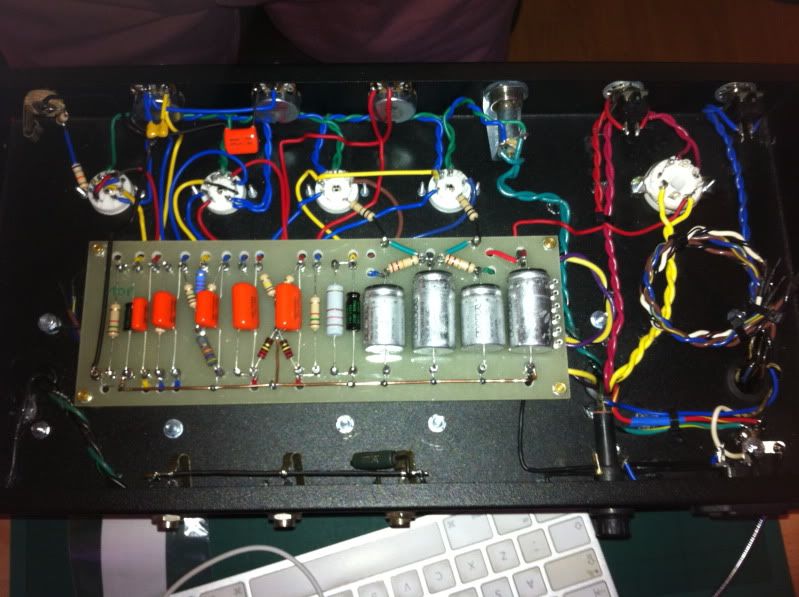
So, as I mentioned in an earlier post, here is a shot of my build and there is a whole album of progress and gut-shots here. Enjoy. Comments/feedback and suggestions more than welcome, I'm looking to do a similar amp again next but with the addition of three separate EQ pots, so any advice would be appreciated.
Thanks again.
Ben
My amp is now finished! I tested all the voltages today and while being a little lower than I expected everything was pretty much where it should be and the lower voltage was consistent and turned out to be because the PT secondary was rated somewhat lower than on the schematic I was following, so it all makes sense.
The amp, to my total amazement, sounds fantastic. I'm so pleased, I was expecting a fail of some kind at first but it's fine and is exactly the sound I was after, a little dirtier than I'd expected but that's even better for the kind of stuff I play when I do play guitar (I'm a drummer mainly). Love it.
There's a bit of buzz when the tone pot is up but it's no more than on other amps I've played and it doesn't bother me a bit.
So, as I mentioned in an earlier post, here is a shot of my build and there is a whole album of progress and gut-shots here. Enjoy. Comments/feedback and suggestions more than welcome, I'm looking to do a similar amp again next but with the addition of three separate EQ pots, so any advice would be appreciated.
Thanks again.
Ben
No kidding.Very nice Ben, very neat and tidy, looks fantastic. Just a pleasure to look at.
Hello Ben,
beautiful build, checked out the other pics and great job on documenting all your excellent work. As you are looking at alternate tone stacks, I would suggest getting a free download to try on following
Duncan's Amp Pages
Very easy to use tone stack calculator , will allow you to simulate different combos of components and look at the response curves. Lots of other good design info too.
- Status
- Not open for further replies.
- Home
- Live Sound
- Instruments and Amps
- Tube Guitar amp, dummy load - Advice needed!