Hi all,
I am thinking of making a simple tube equalizer for my home system, which is mostly DIY and tubed. However, I've never messed with tone controls and just built straight "source through" amps and preamps.
The thing is this, I resurrected a funky transistorized EQ box made for the Electrovoice Interface A speakers from the 70s. I found that I liked the effect it created with my vintage AR speakers - an extended low end and a choice of different treble settings.
As most of my other stuff is tubed, it would be fun to recreate a similar box with preamp tubes instead of transistors, perhaps 6SN7 or 12AU7 or 5687, all of which I have a stash of.
I guess I could take care of the treble boost by using an RC network across an unbypassed cathode resistor, something like a 0,02uF in series with a variable resistor. Am I right? I have seen this in guitar amps to make the sound "bright", but I don't really know the math to calculate the exact values.
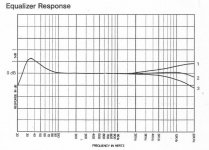
The EV eq box has a very nice extension of just the low end with a peak around 35 Hz, sharply falling off below 30 Hz to free the amp and speakers from having to work unnecessarily with stuff at 20 Hz (unless you have really large speakers, which I don't at the moment).
Would it be possible to create something similar with, say, a 2-stage tube topology? I'm attaching a picture of how the frequency response looks with the EV box connected between source and power amp. I don't expect anyone to do the work for me here, but maybe you could point me to some schematics or computer simulation programs that could let me get the circuit right.
Thankful for any help!
Martin
I am thinking of making a simple tube equalizer for my home system, which is mostly DIY and tubed. However, I've never messed with tone controls and just built straight "source through" amps and preamps.
The thing is this, I resurrected a funky transistorized EQ box made for the Electrovoice Interface A speakers from the 70s. I found that I liked the effect it created with my vintage AR speakers - an extended low end and a choice of different treble settings.
As most of my other stuff is tubed, it would be fun to recreate a similar box with preamp tubes instead of transistors, perhaps 6SN7 or 12AU7 or 5687, all of which I have a stash of.
I guess I could take care of the treble boost by using an RC network across an unbypassed cathode resistor, something like a 0,02uF in series with a variable resistor. Am I right? I have seen this in guitar amps to make the sound "bright", but I don't really know the math to calculate the exact values.
The EV eq box has a very nice extension of just the low end with a peak around 35 Hz, sharply falling off below 30 Hz to free the amp and speakers from having to work unnecessarily with stuff at 20 Hz (unless you have really large speakers, which I don't at the moment).
Would it be possible to create something similar with, say, a 2-stage tube topology? I'm attaching a picture of how the frequency response looks with the EV box connected between source and power amp. I don't expect anyone to do the work for me here, but maybe you could point me to some schematics or computer simulation programs that could let me get the circuit right.
Thankful for any help!
Martin
Attachments
Thanks!
The 10 band eq looks interesting, and does allow for a boost of only the low bass. But I think that is for another day, I was hoping to make this project simpler.
I guess I don't even need controls. It would be ok with just a switch, to go from "flat" to "enhanced" mode in order to bring life into some older speakers.
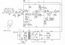
Im posting the schematic for the solid state box that Electrovoice made.
The 10 band eq looks interesting, and does allow for a boost of only the low bass. But I think that is for another day, I was hoping to make this project simpler.
I guess I don't even need controls. It would be ok with just a switch, to go from "flat" to "enhanced" mode in order to bring life into some older speakers.
Im posting the schematic for the solid state box that Electrovoice made.
Attachments
For a simulator, you can try the tone stack calculator (free download) from Duncan Amps.
Just scroll down the screen until you get to Tone Stack Calculator - Free
Just scroll down the screen until you get to Tone Stack Calculator - Free
Thanks again!
The Duncanamps software is nice, and I have tried it before. Seems to be aimed mostly at tone shaping guitar amps though.
Where can I read more about filter designs?
I managed to improve the little EV eq box a little, by replacing the aging electrolytics in the signal path with Wima MKP:s. The power supply also got new computer grade caps. I should just keep it hooked up and forget about it. But I cannot pass a chance to learn about new tube stuff!
I should explain that I'm not an engineer, but I started restoring vintage stuff and then learning to build tube gear in back the '90s.
Several years ago I built my semi-Williamson amp, an RCA type RIAA preamp and some other stuff that I've been listening to since then. A new project would be nice to have.
I also have a couple of dead Quad II that I need output transformers for. But that's expensive.
Have you seen this one before? It's located about half-way down the page here:
http://www.headwize.com/projects/equal_prj.htm
No idea what a 'biophonic' equalizer is? It sounds 'organic' enough, though. heh, heh....
I have had some good luck using SPICE to model/design active equalizer circuits. There are some good models available for the common audio tubes out there, easily found with Google. Enter your schematic into SPICE, and measure the frequency response at various points to see what's happening. Then, adjust the various component values to suit your desired response. This does not replace the actual prototyping of the design in the real world, mind you. It's just a lot easier to 'get in the ballpark' with SPICE before you spend a lot of time on a working prototype unit. Unless you prefer doing things the 'hard way', and then bragging to us mere mortals who cheat our way through this stuff... LOL! 😀
HTH-
- Status
- Not open for further replies.