Any hints as to how to take an amplified differential signal and convert it to a single ended signal? (Without the use of transformers, just discrete tube circuitry)
That is precisely what I was looking for, thank you! (I had be ruminating on the circlotron while considering how to do this, oddly enough!)
I have an upcoming need for the same thing and am thinking of building one of Broskie's 'unbalancers'. Kits are not currently available but should be an easy point to point. The manual for it is here http://www.tubecad.com/2011/11/25/Unbalancer 9-pin.pdf
I'm very pleased with one of his Aikido line stages to drive my F4.
I'm very pleased with one of his Aikido line stages to drive my F4.
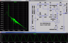
Differential White Cathode Follower
Not better, not worse, just different...
If this old screenshot looks less than great, only cause
I was torturing it with ripple and common mode noise.
10VPP 120Hz ripple, 10VPP 450Hz Common Mode.
Barely see either one in the output...
BroskieCF works just as good under similar torture.
Not better, not worse, just different...
If this old screenshot looks less than great, only cause
I was torturing it with ripple and common mode noise.
10VPP 120Hz ripple, 10VPP 450Hz Common Mode.
Barely see either one in the output...
BroskieCF works just as good under similar torture.
Attachments
Last edited:
I've done it in a much simpler fashion.
Assuming a balanced source, driving an amplifier that is otherwise accepted as having a single-ended input:
Ground is pin one and shield of RCA. Pin 2 of XLR goes to the grid input.
Now the 'tricky' part: pin 3 of the XLR will be used to drive the cathode of the input tube. If a cathode bypass capacitor exists, lift it from ground and tie it to pin 3 of the XLR (when using the RCA input, put a jumper from pin 1 to pin 3 to restore the bypass cap circuit). If it does not exist, calculate the for the correct value and tie it between the cathode of the input tube and pin 3 of the XLR.
While this is obviously not a balanced circuit, it is indeed differential. This technique was originally used by George Philbrick (who is generally accepted as, but is not in fact the inventor of the opamp), in his original opamp circuits.
- Status
- Not open for further replies.
