I have an amplifier which exhibits a form of instability I haven't seen before.
If I slowly ramp up a test signal, and then slowly turn it down, everything looks great.
If I turn it up to clipping, and then quickly turn it off, the amplifier starts to oscillate at a subsonic frequency, the line on the oscilloscope bounces up and down until it does out
The size of the cathode bypass capacitor on the input tube seems to affect the amplitude of the oscillations. When it is large, the amplifier can breaks into a high amplitude oscillation. At the stock capacitor size, it needs to be provoked as described above.
There is no evidence of high frequency oscillation.
Any suggestions to troubleshoot this? I would like to improve the performance of the amplifier such that it no longer oscillates.
Suggestions: A stab in the dark could cause the one yielding the knife to cut himself. Schematic? Or at least the Make and Model Number? Loudspeaker Make and Model Number? Or, are you testing with a Load Resistor? Is the amp all original, or did someone modify it? Those are at least a start to turning the lights on. It is not you, this kind of thread opening is very common, a thread is started with a question, but without any useful information to get the ball rolling.
You need a stiffer (lower impedance) power supply. Bigger smoothing caps *might* be sufficient to cure it. Otherwise we'll need a schematic to offer more 'surgical' advice.
Yes, it could be that your amp has conditional stability at LF so the reduction in gain caused by clipping causes oscillation to start.
You probably have several low-pass RCs in the amp at almost the same frequency. Such as coupling caps between stages loaded by grid leakage resistors, and the cathode C and cathode R.
Usually it is enough to change one of them radically, like making a coupling cap 10 times as large, or the cathode cap much smaller if your lf response allows.
The effect you see is called motorboating for obvious reasons.
Jan
Usually it is enough to change one of them radically, like making a coupling cap 10 times as large, or the cathode cap much smaller if your lf response allows.
The effect you see is called motorboating for obvious reasons.
Jan
1. Its the infamous ussr built Priboi amplifier. The circuit is original, all component values are original except the electrolytic capacitors have been changed and a few resistors.
2. So far, I have tried changing the coupling capacitors to a range of different sizes, and it still does it. I also have tried scoping the power supply, and although it does vary a bit when the amp is oscillating, it isn't much at all. The decoupling capacitors on the power supply for the front end are unusually large.
3. I am driving an 8 ohm resistive load.
4. This was provoked by changing the cathode bypass capacitor on the input tube to a larger value 100uF instead of 20uF, in an attempt to make the amplifier sound better. Instead of sounding better, it began to oscillate. I tried to mitigate this by changing one of the coupling capacitors to a smaller value, with a -3dB poi t of 60Hz. This was ineffective, even that didn't stop the oscillation, only the bypass capacitor makes it semi stable.
The stock value (20uF) keeps the amplifier from oscillating constantly, but the bouncing under transients shows me it is on the verge of instability.
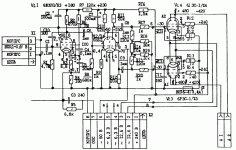
5. See attached schematic. Thank you very much for ideas and help!
2. So far, I have tried changing the coupling capacitors to a range of different sizes, and it still does it. I also have tried scoping the power supply, and although it does vary a bit when the amp is oscillating, it isn't much at all. The decoupling capacitors on the power supply for the front end are unusually large.
3. I am driving an 8 ohm resistive load.
4. This was provoked by changing the cathode bypass capacitor on the input tube to a larger value 100uF instead of 20uF, in an attempt to make the amplifier sound better. Instead of sounding better, it began to oscillate. I tried to mitigate this by changing one of the coupling capacitors to a smaller value, with a -3dB poi t of 60Hz. This was ineffective, even that didn't stop the oscillation, only the bypass capacitor makes it semi stable.
The stock value (20uF) keeps the amplifier from oscillating constantly, but the bouncing under transients shows me it is on the verge of instability.
5. See attached schematic. Thank you very much for ideas and help!
Attachments
As I can see, C3, C6 and C8 are 1µF, which are too large.
Try to measure the B+ bus when the amp is oscillating, hooking one test lead of the oscillo to the amp output and the other to B+, in the AC mode or placing a cap in series to see the AC amplitude of the oscillation.
Try to measure the B+ bus when the amp is oscillating, hooking one test lead of the oscillo to the amp output and the other to B+, in the AC mode or placing a cap in series to see the AC amplitude of the oscillation.
Here is how it behaves with all stock component values.
YouTube
Clipping is about 70W. You see when I turn it up to clipping and then back down slowly, it behaves normally
When I turn it up slowly and down quickly, you can see the waveform bouncing up and down slightly (assuming you can see it with my shaky camera holding!). Increasing C5 increases this effect until at 100uF the amp is unstable, and a transient can throw it into full blown oscillation. I am hesitant to try that again for fear of damaging the output tubes.
Changing the coupling capacitors to smaller values did not affect this stability. I tried C8=C9= 0.22uF and C6=0.047uF
Could you measure the supply rails caps to know if any is degraded or open?
They are all Panasonic caps which are about 4 years old.
I can measure them, but I dont really suspect them - especially since there is no hum, and both channels behave the same way.
1. Its the infamous ussr built Priboi amplifier. The circuit is original, all component values are original except the electrolytic capacitors have been changed and a few resistors.
2. So far, I have tried changing the coupling capacitors to a range of different sizes, and it still does it. I also have tried scoping the power supply, and although it does vary a bit when the amp is oscillating, it isn't much at all. The decoupling capacitors on the power supply for the front end are unusually large.
3. I am driving an 8 ohm resistive load.
4. This was provoked by changing the cathode bypass capacitor on the input tube to a larger value 100uF instead of 20uF, in an attempt to make the amplifier sound better. Instead of sounding better, it began to oscillate. I tried to mitigate this by changing one of the coupling capacitors to a smaller value, with a -3dB poi t of 60Hz. This was ineffective, even that didn't stop the oscillation, only the bypass capacitor makes it semi stable.
The stock value (20uF) keeps the amplifier from oscillating constantly, but the bouncing under transients shows me it is on the verge of instability.
5. See attached schematic. Thank you very much for ideas and help!
The obvious solution is to change the cathode cap back to 20uF. It's value has no effect on the sound other than the LF roll off. If the bass is good enough there is no reason to change it. By increasing it 5 times you increased the LF gain 5 times which can be enough to provoke LF oscillations.
Another issue may be the unusually large supply caps, that can also provoke it. That you see only small variation on the supply doesn't mean a lot.
Edit: what is the value of the cathode resistor?
Jan
Could you measure the supply rails caps to know if any is degraded or open?
If degraded or open the effect would not be there, obviously.
Jan
If decoupling caps are degraded, power buses are an excellent way to couple stages between them causing motorboating or oscillations.
There seems to be some confusion what causes this motorboating. It is caused by having too much capacitance in the power supply and the coupling capacitors, which makes for lots of phase shifts at the low end while there is still LF gain. If the LF roll-off points are close together, the phase shift accumulates to 180 deg while there is still gain, and there you go.
Decreasing capacitance at one or more points avoids having all the roll off at the same frequency and usually fixes it. I agree with Osvaldo that the power supply caps play here but obviously it was caused by increasing 5x the cathode cap, not by a power supply cap gone bad.
In this case it is clear, raising the cathode cap 5x pulls the LF roll off at the cathode down 5 times, which mean you now have lots more gain at not-so-low frequencies and also additional phase shift there and there you go!
Jan
Last edited:
1. The cathode resistor of the EF86 is 6.8k ohms. It is incorrectly shown in the schematic as 6.8 ohms, which is incorrect.
2. I do have the amplifier back to stock, but the instability is still noticeable as shown on the YouTube video. Basically, there is some bouncing of the waveform after a large transient. If I change the vertical scale of the oscilloscope, the oscillation becomes much more obvious - it is quite small in amplitude. When the cathode cap was increased by 5x, the oscillation was rail to rail, and did not stop or die down. My objective is to try and find the source of this oscillation, and make the amplifier behave properly such that there is no oscillation after a transient.
3. If I pull the EF86, and inject a signal at the grid of the second stage, there is zero bouncing - it is definitely related to the driver tube, and the negative feedback loop.
4. The decoupling capacitors are of recent manufacture, and are in good shape. I do wonder now, if this is related to the time constant of R7 and C2?
5. The instability remains, with all of the 1uF coupling capacitors changed to more usual values - it is not just because of them.
6. Thanks for all of the response, I really appreciate it.
7. Square waves look quite good - very little ringing and nice and flat. This appears to me to be a low frequency issue, so I have not yet added grid stoppers, or anything like that. I am considering reducing C2 from 100uF to 10uF just for a test, to see if it has any effect. When I designed a feedback amplifier some years ago, I think I used 10uF decoupling capacitors, and I never experienced any low end instability.
One more thing. The biasing scheme for the EF86 is very weird. It has both cathode bias, and grid leak bias. This amplifier has way too much gain in general. To the extent that I had to make attenuating cables, so I didn't hear hiss from my preamplifier. If I was able to reduce the gain of the EF86, I think it would go a long way towards curing the stability issue, because it would put the 180 degree phase shift at low frequency well below unity gain under all conditions.
The risk here, is I believe the high impedance EF86 also plays a role in maintaining high frequency stability, so if I do make any changes I will have to evaluate if the square wave still looks nice.
Additional information:
1. With R4 shunted, 0.02V gives 22.5V out With R4 not shunted, 0.55V gives 22.5V out This means gain negative feedback is 28.8dB.
2. With C8 and C9 changed to 0,22uF, amplifier becomes unstable
3. With C6 changed to 0.022uF, amplifier becomes unstable.
4. Open loop gain (stock), is flat to 15Hz, the limit of my oscillator. I cannot see any lower than this, but it has serious subsonic response
5. Closed loop gain (stock), is flat to 15Hz too
6. Open loop gain rolls off slowly above 10kHz, but hard to tell by how much, as I wasn't using the correct meter with extended HF response.
I guess the issue here, is how to cut off the response inside the feedback loop, so that gain < 1 when the low frequency phase reversal occurs. Smaller coupling caps tend to just raise the frequency of oscillation.
Also, I found a way better schematic
http://knob.planet.ee/fix/priboi/Priboi_Original.pdf
To help determine the root cause of this instability, you can start by disconnecting the feedback loop and then see if a step response still causes this instability..... Based on these results, can make a determination on the cause.. If you have a scope....look a the envelope of the oscillation and settling time.. this can tell you the frequency and Q of the instability.... These are clues to help narrow down the area.... I wish you lived closer.... I have a HP Network Analyzer I can let you use to look at the BODE plot for Phase and Gain margin....this tool will help locate the problem in minutes...
Measure the primary inductance of your output transformer. The OPT may in fact be the dominant pole in your feedback loop. And the actual powered inductance may be less than you think it is (See * below) Measure 2 ways:
Unpowered: (caution, make sure all capacitors are discharged). First of all, the whole amplifier must floating (No connections to inputs, speakers, power cord, or any other ground. (This unpowered test does not require any unwiring of your amplifier parts). Measuring it with No DC is an easy measurement if you have an oscillator, a 2 channel scope, and a resistor that is equal to the 'rated' primary impedance. Circuit: Oscillator 'Hot' out to the resistor, the resistor to one plate lead of the primary, the other plate lead of the primary to ground and the oscillator output 'return' to ground. Put channel 1 probe tip on the junction of the oscillator 'hot' and top of the resistor, and probe ground on ground. Put channel 2 probe tip on the junction of the resistor and the plate lead of the primary, and the probe ground to ground.
Turn your oscillator frequency until channel 2 waveform is 0.707 of the channel 1 waveform. Example, channel 1 is 5 Volts, and channel 2 is 3.5 Volts. Now, check your work, the phase between channel 1 and channel 2 should be about 45 degrees. This works for un-balanced (single ended) oscillator outputs, and balanced oscillator outputs.
The unpowered inductance of your OPT primary is calculated as follows:
Resistance of the resistor you used. Lets say you used a 5k Ohm resistor.
f = the frequency where the channel 2 amplitude reduced to 0.707 of the channel 1 amplitude.
L = the primary inductance
pi = 3.14 (to 3 places)
R = 2 x pi x f x L
5000 Ohms = 2 x pi x f x L L = 5000/(2 x pi x f)
example: f = 20 Hz L = 5000/(2 x 3.14 x 20 Hz) L = 39.8 henry
If your oscillator does not go low enough, then test for the -1dB bandwidth (0.89 of the original voltage). The low frequency -1 dB bandwidth of the OPT is one octave away from the - 3dB bandwidth. Just measure -1 dB, and calculate L using f(-3db) = 1/2 x f (-1dB).
Powered OPT inductance test: Disconnect the global negative feedback. Put an 8 Ohm resistor on the 8 Ohm output tap, and common (should be grounded). Use very low voltage out of the oscillator (the amp has Lots of gain, without negative feedback). Connect the scope channel 1 probe to 8 Ohm tap, and probe ground to common output. Connect the scope channel 2 probe to one output tube control grid, and probe ground to ground.
Step 1 Set the oscillator to 1 kHz, and 1 Volt on channel 1 (1V on 8 Ohm tap). Measure channel 2 voltage (output tube control grid).
Step 2 Tune the oscillator to lower frequencies, until channel 1 reads 0.707V (-3dB). Check that channel 2 voltage is not also reduced nearly as much as 0.707 of the channel 2 voltage in step 1 (reduced by 10%, is -1dB). If only channel 1 voltage is significantly reduced 0.707), and channel 2 voltage is not reduced very much, then the output transformer is the dominant pole. That is the -3dB point of the OPT.
This 2nd test (* see above), shows the result of the actual primary inductance which can be reduced by the presence of DC current that is un-balanced by the Push tube having different quiescent current than the Pull tube.
Which brings to mind, did you check that the DC quiescent current of Push tube was the same as the DC quiescent current of the Pull side?
Last edited:
To help determine the root cause of this instability, you can start by disconnecting the feedback loop and then see if a step response still causes this instability..... Based on these results, can make a determination on the cause..
It does not. When the loop is opened, the amplifier is absolutely stable, and doesn't have any sort of tendency to oscillate.
If you have a scope....look a the envelope of the oscillation and settling time.. this can tell you the frequency and Q of the instability.... These are clues to help narrow down the area....
I have the scope set to the longest timebase it has, and the wavelength is still much too long to fit on the screen. I estimate it is oscillating at maybe 1-5Hz or so, if I had to guess, and it looks sinusoidal from what part of the waveform I can see - basically just the zero line of the scope bouncing up and down with a slight arc to it.
As for settling time, I would say a matter of a couple seconds. I will make a quick video on Sunday when I'm back in the city.
Which brings to mind, did you check that the DC quiescent current of Push tube was the same as the DC quiescent current of the Pull side?
Yes, the tubes are set correctly. Also, the oscillation is identical on both channels. I think this may be one of the reasons this amplifier has a reputation for instability.
I have only a single channel oscilloscope, but I can do this test using my VTVM. Thank you for taking the time to post this, I will post the results once I've done the test. I believe the test may be compromised by the fact that my oscillator's low end range ends at 15Hz, because when I tested the amplifier open loop, the response was down 0dB at 15Hz relative to 1kHz.Step 1 Set the oscillator to 1 kHz, and 1 Volt on channel 1 (1V on 8 Ohm tap). Measure channel 2 voltage (output tube control grid). <snip>
WOW..... that is a wacky situation.... One time I did have a almost similar situation and the cause was that the Output Transformer secondary common lead was not grounded to the chassis... ie the secondary was floating because the speaker jack was also isolated off chassis.... Once I connected the common to chassis , the problem was solved... Maybe start looking for an incorrect value in the FB circuit...Did this amp ever work nicely at one time ?? Also, if the ESR has climbed in main filter caps this can also cause phase shift ...
Your Open loop frequency response is not even rolled off by 1 dB at 15 Hz? Wow! And careful, some VTVM AC measurements may not all have a flat frequency response from 1Hz to 1kHz. And why would anybody use a 4.7Meg resistor to create grid leak bias for an EF86? How much would you like the bias to be? ? ?
Last edited:
- Home
- Amplifiers
- Tubes / Valves
- Tube amplifier stability question