Hello--
I know there are a lot of posts about this. I've read them over the past couple days and am still having trouble formulating a plan to correct an issue with my latest amplifier. It sounds great but am hunting down a 60hz buzz I can hear from the speakers--not very loud, but loud enough to hear from the couch.
In particular, I'm not sure I understand signal where signal in / signal out / potentiometer housing / chassis fit in. Am soliciting advice so I can minimize time wasted chasing this down and try to educate myself.
On the bench, when this was all just a mess of sockets and wiring, I could easily ground every connection at a single point. It was dead silent. Transferring it to the chassis, I haven't been able to easily accomplish that same approach. An extra challenge to this build is constructing the amplifier out of a chassis with separable top and bottom, and have wires which need to connect from bottom to top and vice versa.
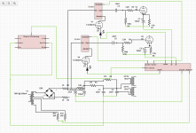
Attaching a diagram of my power supply and grounding scheme. The line on the right hand side is a small length of copper wire. This is a 45 amplifier driven by gyrator-loaded 6N23P. I am using Rod Coleman regulators. So "Cathode x4" is a bit simplistic, indicating the following:
From there, a single wire goes to a terminal strip which is connected to signal in (1 pair of RCA, 1 bluetooth PCB module) and signal out (the output from my Alps potentiometer, which has a metal housing). I have a DPDT switch to toggle between RCA in and bluetooth in. Bluetooth is L-C-R molex.
I have the potentiometer housing grounded to the bus bar, as you can see, and because of this, the chassis is also connected to the bus bar.
The IEC inlet ground plug is connected to chassis near the IEC inlet.
Heater center tap is virtual, constructed with a pair of 220 ohm resistors.
Not pictured: bleeder resistor across C4; 30 ohm resistors between rectifier (+ and - ) and C1.
My thinking is that I need to correct C2 -> C1 and make it C2 -> C3. That seems to be the correct approach here. But is that all I need to eliminate the buzz? I feel like there's something I'm missing involving the signal grounding and/or heater CT.
Really appreciate any advice!

I know there are a lot of posts about this. I've read them over the past couple days and am still having trouble formulating a plan to correct an issue with my latest amplifier. It sounds great but am hunting down a 60hz buzz I can hear from the speakers--not very loud, but loud enough to hear from the couch.
In particular, I'm not sure I understand signal where signal in / signal out / potentiometer housing / chassis fit in. Am soliciting advice so I can minimize time wasted chasing this down and try to educate myself.
On the bench, when this was all just a mess of sockets and wiring, I could easily ground every connection at a single point. It was dead silent. Transferring it to the chassis, I haven't been able to easily accomplish that same approach. An extra challenge to this build is constructing the amplifier out of a chassis with separable top and bottom, and have wires which need to connect from bottom to top and vice versa.
Attaching a diagram of my power supply and grounding scheme. The line on the right hand side is a small length of copper wire. This is a 45 amplifier driven by gyrator-loaded 6N23P. I am using Rod Coleman regulators. So "Cathode x4" is a bit simplistic, indicating the following:
- 2x 6N23P cathodes connect there as separate connections
- 1 wire bringing the left 45 cathode + cathode resistor + cathode decoupling capacitor + grid leak resistor
- 1 wire bringing the right 45 cathode + cathode resistor + cathode decoupling capacitor + grid leak resistor
From there, a single wire goes to a terminal strip which is connected to signal in (1 pair of RCA, 1 bluetooth PCB module) and signal out (the output from my Alps potentiometer, which has a metal housing). I have a DPDT switch to toggle between RCA in and bluetooth in. Bluetooth is L-C-R molex.
I have the potentiometer housing grounded to the bus bar, as you can see, and because of this, the chassis is also connected to the bus bar.
The IEC inlet ground plug is connected to chassis near the IEC inlet.
Heater center tap is virtual, constructed with a pair of 220 ohm resistors.
Not pictured: bleeder resistor across C4; 30 ohm resistors between rectifier (+ and - ) and C1.
My thinking is that I need to correct C2 -> C1 and make it C2 -> C3. That seems to be the correct approach here. But is that all I need to eliminate the buzz? I feel like there's something I'm missing involving the signal grounding and/or heater CT.
Really appreciate any advice!
Last edited:
That wire that goes from C3 to C1, should go from C3 to C2 instead.
C1 has all the high ripple current.
C1 has all the high ripple current.

I understand that this is a rudimentary drawing, so maybe I'm not getting the whole picture.
But if I look at the signal in and signal out grounding, that is somewhere halfway a return line that can be expected to carry hum current.
The potmeter ground is at another point so there may be a hum level differences between the signal ground points and the pot ground points. I would connect these points all at the same point.
Also I don't see the need to connect the chassis to any of those points. The chassis should only be connected to PE.
If needed, connect the sigbnal ground point to chassis via diodes/R/C to isolate it from direct signal ground but keep the safety ground intact.
Does the hum level change when you vary the volume?
Jan
Apologies for the basic drawing. I was trying to keep the representation as simple but as accurate as possible.
Have never done this before, but attempted a schematic using Digi-Key's online tool.
The schematic is trying to emphasize grounding arrangement and is not a great "traditional" schematic.
Not pictured:
The pink-ish rectangle on the right is my ground bus wire.
Potentiometer is Alps. I measure continuity between GROUND IN and GROUND OUT on the potentiometer. GROUND IN/OUT are not continuous with potentiometer housing.
Input connections have been simplified (RCA, Bluetooth) and only show ground connection and not the L/R and switch wiring.
Transformer shows two secondaries: 300-0V for amplifier power and 6.3-0V for 6N23P heaters.

Have never done this before, but attempted a schematic using Digi-Key's online tool.
The schematic is trying to emphasize grounding arrangement and is not a great "traditional" schematic.
Not pictured:
- OPT connections to speakers. Speaker/OPT negative is not grounded anywhere.
- RCA in
- Bluetooth in
- Signal to 6N23P grids. These are directly coupled from the potentiometer.
The pink-ish rectangle on the right is my ground bus wire.
Potentiometer is Alps. I measure continuity between GROUND IN and GROUND OUT on the potentiometer. GROUND IN/OUT are not continuous with potentiometer housing.
Input connections have been simplified (RCA, Bluetooth) and only show ground connection and not the L/R and switch wiring.
Transformer shows two secondaries: 300-0V for amplifier power and 6.3-0V for 6N23P heaters.
Attachments
Last edited:
I can no longer edit the previous post, but R2 is definitely connected to the negative terminal of C1!
The volume of the buzz does not change with the volume control or input selection.I understand that this is a rudimentary drawing, so maybe I'm not getting the whole picture.
But if I look at the signal in and signal out grounding, that is somewhere halfway a return line that can be expected to carry hum current.
The potmeter ground is at another point so there may be a hum level differences between the signal ground points and the pot ground points. I would connect these points all at the same point.
Also I don't see the need to connect the chassis to any of those points. The chassis should only be connected to PE.
If needed, connect the sigbnal ground point to chassis via diodes/R/C to isolate it from direct signal ground but keep the safety ground intact.
Does the hum level change when you vary the volume?
Jan
Before grounding the potentiometer housing (which also brings the chassis into play), moving the volume control would modulate a hum--at max volume, low hum. Below that, the hum would increase at about half, then decrease at 0 volume--or when I touched the bare metal shaft.
There is no wire running between potentiometer ground in and ground out, as I measure continuity there.
Here's my attempt at showing the potentiometer, switch, RCA, and bluetooth wiring:
Last edited:
I see no connection between the two halves of the pot.
Also, I have the impression that the pot isn't connected correctly, or the pinout/pot isn't shown correctly.
Can you redraw with the normal pot symbol of two variable resistors, including the rest of the drawing? Hard to get an overview.
It is a complete system with multiple grounds, and you really need to look at the full picture.
Jan
I realize now I have incorrectly drawn the schematic for C3/C4.Can you post photos of the wiring?
The "star point" I had indicated for C3 is actually at the negative terminal of C4.
So C1 (-) is directly connected to C4 (-), then C4 (-) is connected to C3 (-).
Something I will correct in line with your earlier comment about C3 -> C2.
It is difficult to see, but gyrator B+ from C2 is NOT connected directly to (+) terminal of C3.
Detail of terminal block:
Showing propped open (bluetooth signal connection dangling to the left; must disconnect to open lid this far):
I have an acrylic cover for the PCB elements but this is not yet in place.
Last edited:
Hi Jan--I see no connection between the two halves of the pot.
Also, I have the impression that the pot isn't connected correctly, or the pinout/pot isn't shown correctly.
Can you redraw with the normal pot symbol of two variable resistors, including the rest of the drawing? Hard to get an overview.
It is a complete system with multiple grounds, and you really need to look at the full picture.
Jan
I will attempt to add to the schematic later today.
If by "connection between two halves of the pot" you mean input to output, there is a PCB element which accomplishes this. Then of course each potentiometer out connection is directly coupled to grid of 1 6N23P.
Before wiring, I measured connectivity between signal IN GROUND and signal OUT GROUND on the potentiometer. This must be accomplished also by the PCB.
I apologize for not mentioning the PCB earlier. Again, I'm trying to avoid too many details but apparently am making things more difficult as a result. The amplifier works perfectly aside from this buzz--RCA input, bluetooth input, volume control are all functioning as expected and playing music beautifully.
Last edited:
For those who are still with me, here's what I did this evening to see if I could make some progress:
At this point, I am left with trying to move the potentiometer so that it is not above the B+ connections.
Since the volume of the 120Hz buzz does not change with the pot, does that narrow the possibilities to the pot placement or a ground loop?
When I had this all wired up on the bench, I did not have this noise
- Identified the frequency of the noise as 120Hz
- Rerouted one of the output transformers leads above the chassis, trying to determine if the choke was radiating the noise. No change.
- Disconnected power to the transformer powering the Bluetooth module. No change.
- Rerouted C3/C4 (-) terminals to connect to C2. No change.
At this point, I am left with trying to move the potentiometer so that it is not above the B+ connections.
Since the volume of the 120Hz buzz does not change with the pot, does that narrow the possibilities to the pot placement or a ground loop?
When I had this all wired up on the bench, I did not have this noise
Forgot to mention, I also experimented with:For those who are still with me, here's what I did this evening to see if I could make some progress:
- Identified the frequency of the noise as 120Hz
- Rerouted one of the output transformers leads above the chassis, trying to determine if the choke was radiating the noise. No change.
- Disconnected power to the transformer powering the Bluetooth module. No change.
- Rerouted C3/C4 (-) terminals to connect to C2. No change.
At this point, I am left with trying to move the potentiometer so that it is not above the B+ connections.
Since the volume of the 120Hz buzz does not change with the pot, does that narrow the possibilities to the pot placement or a ground loop?
When I had this all wired up on the bench, I did not have this noise
- The heater center tap (disconnecting/relocating it to C1(-)). When not connected, also got some 60Hz noise. Connected to ground bus is better.
- Disconnecting/connecting the potentiometer housing and chassis ground. No change.
Realized that I could easily prop up the top lid to get extra distance (a few inches) between the potentiometer and the B+ terminal connections. There was no change.
My PSUD2 simulation indicates that I should have vanishingly small ripple in the power supply by C3/C4, and the gyrators have very good PSRR.
I'm really not sure what else to pursue at this point. If it were related to wiring, I would expect that I could see some difference between channels. But the noise measurement is very close between the two. The same goes for switching between bluetooth and RCA input--same noise levels.
Since the buzz volume doesn't vary with the potentiometer setting, I struggle to know what to make of it.
Last edited:
So when you tested the amp on the bench, and it was silent, was that a single channel?
And now when you combine TWO channels in a case, it hums?
That would be a giveaway to ground loop in the wiring.
Jan
And now when you combine TWO channels in a case, it hums?
That would be a giveaway to ground loop in the wiring.
Jan
Nope. It was both channels. I mock up my amplifier in PDUD2 as shown above to try to more accurately model the entire circuit. I'm probably doing that wrong, too!
The only difference, aside from wire routing and placement, is the grounding. The grounding is not all that different--I had multiple star grounds instead of a bus wire. It was all quite haphazard on the bench.
I will think about layout changes I can make but am running out of ideas on tweaks to the grounding scheme.
PDUD2 doesn't model the wiring and its resistance and inductance so that won't help.
You need to find some strech of wiring that carries supply currents, and that therefor develops a very small hum voltage on two points along its length that end up as input voltage at the input.
Can be hard.
Jan
You need to find some strech of wiring that carries supply currents, and that therefor develops a very small hum voltage on two points along its length that end up as input voltage at the input.
Can be hard.
Jan
Yes, I only posted the PSUD2 simulation to support that I don't think the issue is power supply ripple.PDUD2 doesn't model the wiring and its resistance and inductance so that won't help.
You need to find some strech of wiring that carries supply currents, and that therefor develops a very small hum voltage on two points along its length that end up as input voltage at the input.
Can be hard.
Jan
Today I re-wired the (-) terminals of C1 and C2 so that they meet at C3 (-) along with C4 (-). There is then a length of wire that runs to the star grounding point. My ground bus connects there, along with my signal ground.
This actually resulted in about 8 dB more 120Hz noise!
Then I connected that star ground point to the chassis and was back at ~ -76dB 120Hz noise--about exactly what I was measuring yesterday before making the changes.
So reducing wire length wherever possible should address the buzz?
I think the only differences now between my setup "on the bench" is:
- The 60 Ohm resistance I showed modeled in PSUD2 is split between two 30 ohm resistors. One is between the rectifier (-) and the other is between the rectifier (+) and C1 (-/+). On the bench, these were in series between rectifier (+) and C1 (+). I thought splitting them would be more "balanced" but perhaps this is bad?
- Metal chassis. My prototype stage was built onto wood.
I don't have an oscilloscope, but I do have a multimeter. Is it possible to measure the hum voltage? I measured DC at the grid of the 2A3 and found ~30mV. I measured DC and AC from bus bar to chassis ground and found .001V AC and .1V DC.
I can also try to use shielded wire from the potentiometer out to the 6N23P grids. My 45 plate supply runs right over that wiring.
Here's what my phone's frequency spectrum analyzer shows at the cone of my speakers. Both are basically identical.
Please ignore my saying "2A3" in the last post--that is what I use in my other amp and am daftly using it for this amp! This is a 45 amplifier.Yes, I only posted the PSUD2 simulation to support that I don't think the issue is power supply ripple.
Today I re-wired the (-) terminals of C1 and C2 so that they meet at C3 (-) along with C4 (-). There is then a length of wire that runs to the star grounding point. My ground bus connects there, along with my signal ground.
This actually resulted in about 8 dB more 120Hz noise!
Then I connected that star ground point to the chassis and was back at ~ -76dB 120Hz noise--about exactly what I was measuring yesterday before making the changes.
So reducing wire length wherever possible should address the buzz?
I think the only differences now between my setup "on the bench" is:
- The 60 Ohm resistance I showed modeled in PSUD2 is split between two 30 ohm resistors. One is between the rectifier (-) and the other is between the rectifier (+) and C1 (-/+). On the bench, these were in series between rectifier (+) and C1 (+). I thought splitting them would be more "balanced" but perhaps this is bad?
- Metal chassis. My prototype stage was built onto wood.
I don't have an oscilloscope, but I do have a multimeter. Is it possible to measure the hum voltage? I measured DC at the grid of the 2A3 and found ~30mV. I measured DC and AC from bus bar to chassis ground and found .001V AC and .1V DC.
I can also try to use shielded wire from the potentiometer out to the 6N23P grids. My 45 plate supply runs right over that wiring.
Here's what my phone's frequency spectrum analyzer shows at the cone of my speakers. Both are basically identical.
View attachment 1100384
It is very unusual to have a star ground AND a ground bus. I think it would be very difficult to keep control over which ground current runs where.
There should be a single point where the signal ground is connected to the chassis, and that connection preferably through something like 10 ohms to define the ground but avoid current. That R can be shunted by 0.01uF to ground any RF.
The RCA inputs should be mounted isolated from chassis, and both the hot and ground line from the connector should both be brought to the signal ground point of the input stage, say the grid bias and the cathode resistor ground point. Chain that ground to the next stage signal ground point, at its cathode/grid bias R, etc. Nowhere this is connected to chassis.
Bring the power supply B+ to the output stage in the same way, bring the neg side of the last power supply cap to the output stage ground point, probably the point where the two cathode Rs are brought together (for PP). At that point the signal ground that is propagated from input to output connects to the power supply ground coming from the final psu cap.
Details may differ but you get the point, move the signal from stage to stage with its ground line, only interconnect to psu ground at one point, preferably at the output stage.
Connect that final stage ground to chassis through an R.
Note that the psu ground runs directly from output stage to psu cap, and nowhere does that share any wiring with a signal return.
Edit: if you have local stage B+ decoupling caps connect the neg pin of those caps to ground at the output stage ground point, not at the stage ground point. If you would do that you'd send ripple current from the decoupling cap though signal ground, causing a ripple signal between two stages.
Jan
Last edited:
- Home
- Amplifiers
- Power Supplies
- Trying to Understand Ground Loop Problem