Hey guys,
This seemed like a pretty good place for technical knowledge on these things..
So long story short I have a old ZR360 that I got ages ago but has sat unused till just lately, I got it under the understanding that it needed work.
I powered it up, it got hot, yellow and red lights were on, so I shut it down and took it apart.
Found a shorted TIP35C transistor. Also found some dodgy work that someone else had done. I *think* there is supposed to be a inline fuse to protect the RCAs, that was missing and had a piece of wire soldered in its place. I assume that is supposed to be a fuse? Anyone have any idea what value it needs to be?
I also was reading that all transistors on the channel should be replaced when one goes bad.
If I understand this right the TIP35Cs are on the negative rail, do I need to replace just those or the TIP36s that are on the positive rail too.
I should post a few pictures, I can't tell if some other mosfets have been changed. but someone has worked in that area.
thanks for any help!
I was hoping the Kicker tech would visit. Until he does...
I would replace all of the outputs in the blown channel. Check the emitter resistors as well.
TIP35s are on the positive rail, if I'm not mistaken.
If the solder pad/screw hold near the transformer is electrically connected to the transformer secondary, I'd use a nylon screw to screw the board down there.
Can you post a photo where you believe a fuse should be?
Ok, here's what I got.
for whatever ends I cannot upload to my webspace right now, so lets see if attaching works
When I opened it up I was greeted with some pretty gnarly work around the RCAs, I've since cleaned it up and revealed a few pads that that I think once held a fuse.
There is still evidence of work being done elsewhere. Not sure what to make of that. I can only assume its ok since I don't have a good schematic for the ZR360.
I pulled a few of the suspect TIP35Cs to confirm that the one was shorted
Use the 'go advanced' and then 'manage attachments' buttons to load the images to the forum server.
Ok Finally got my webspace sorted out and was able to upload again.
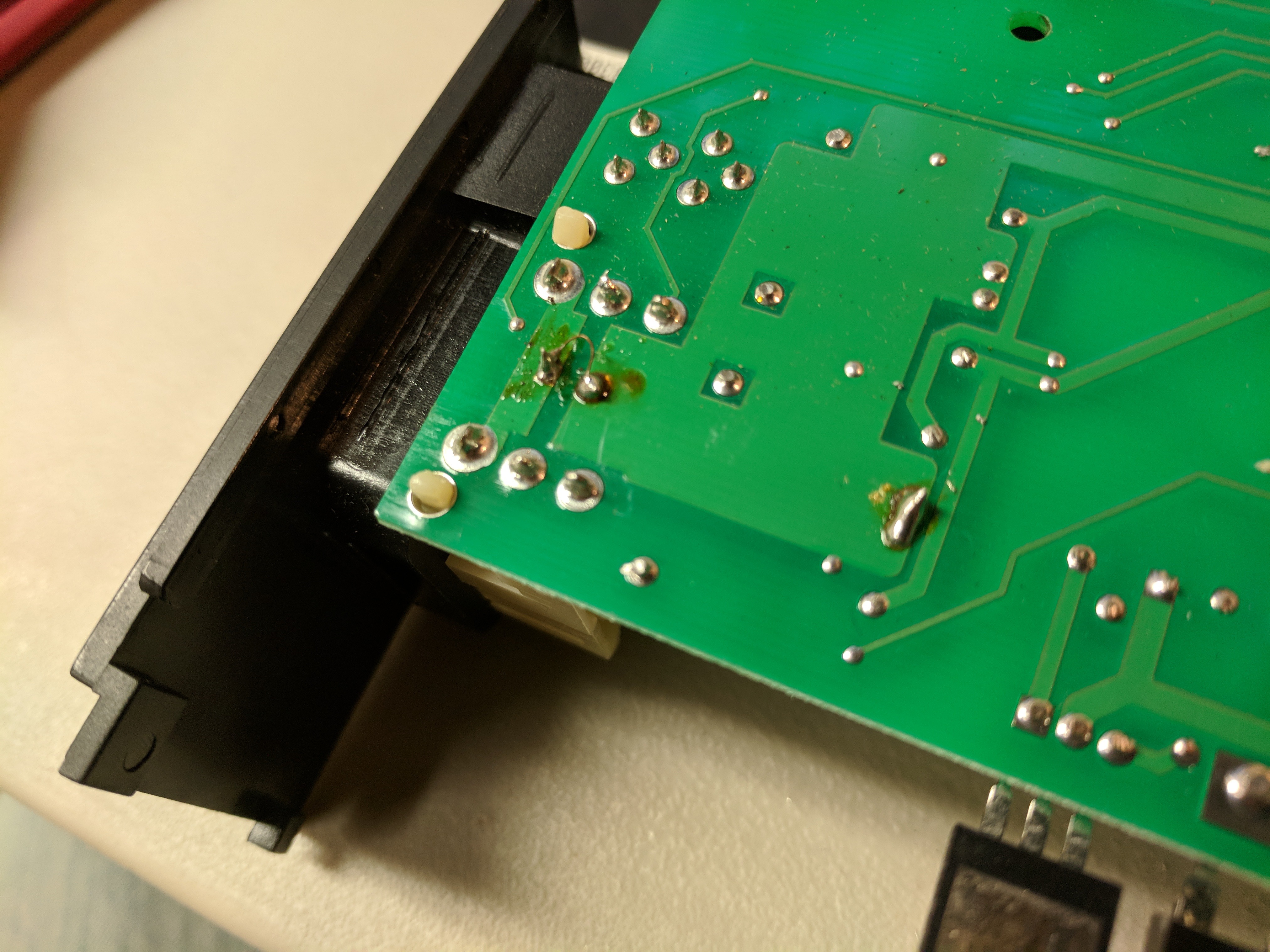
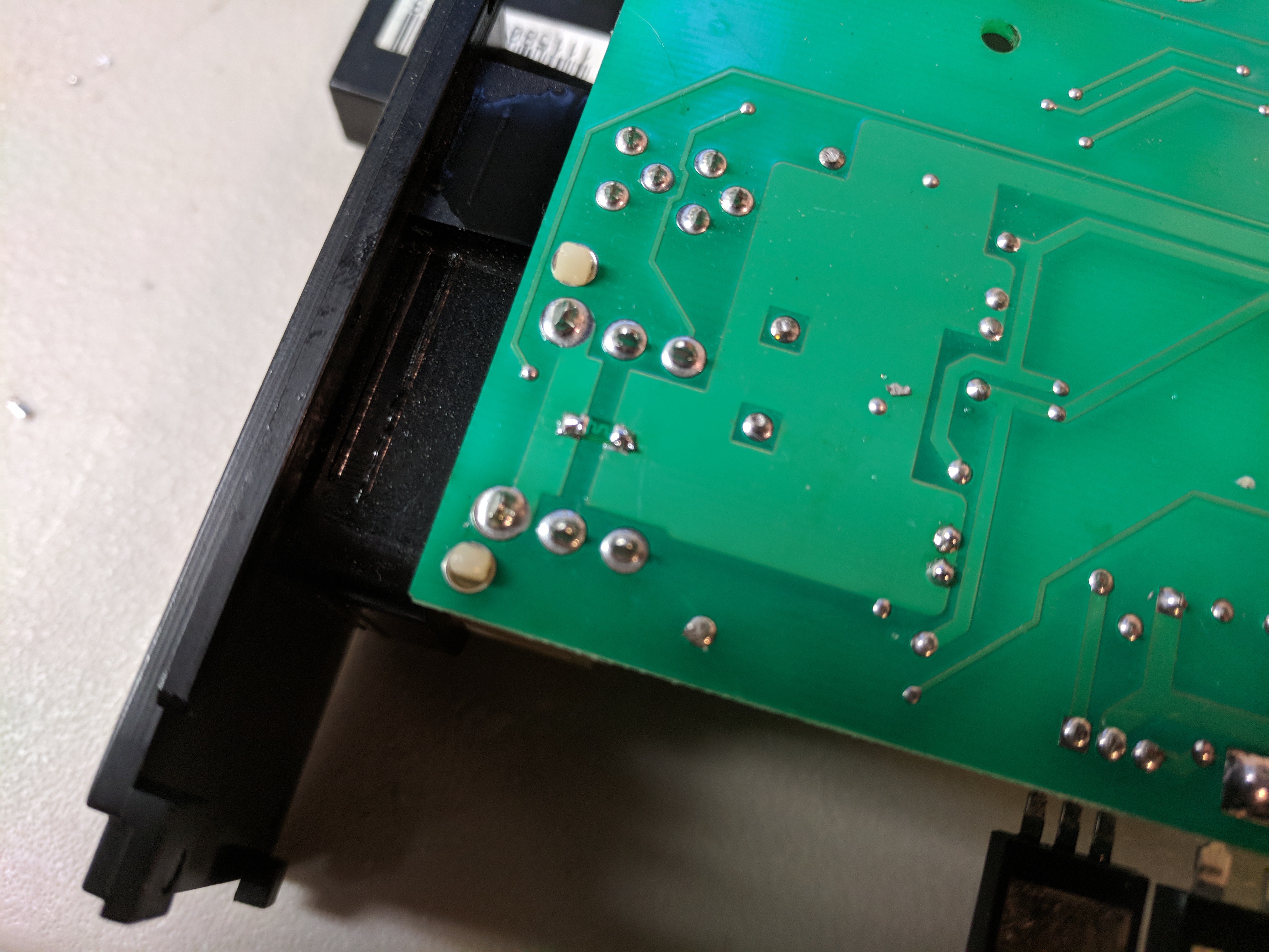
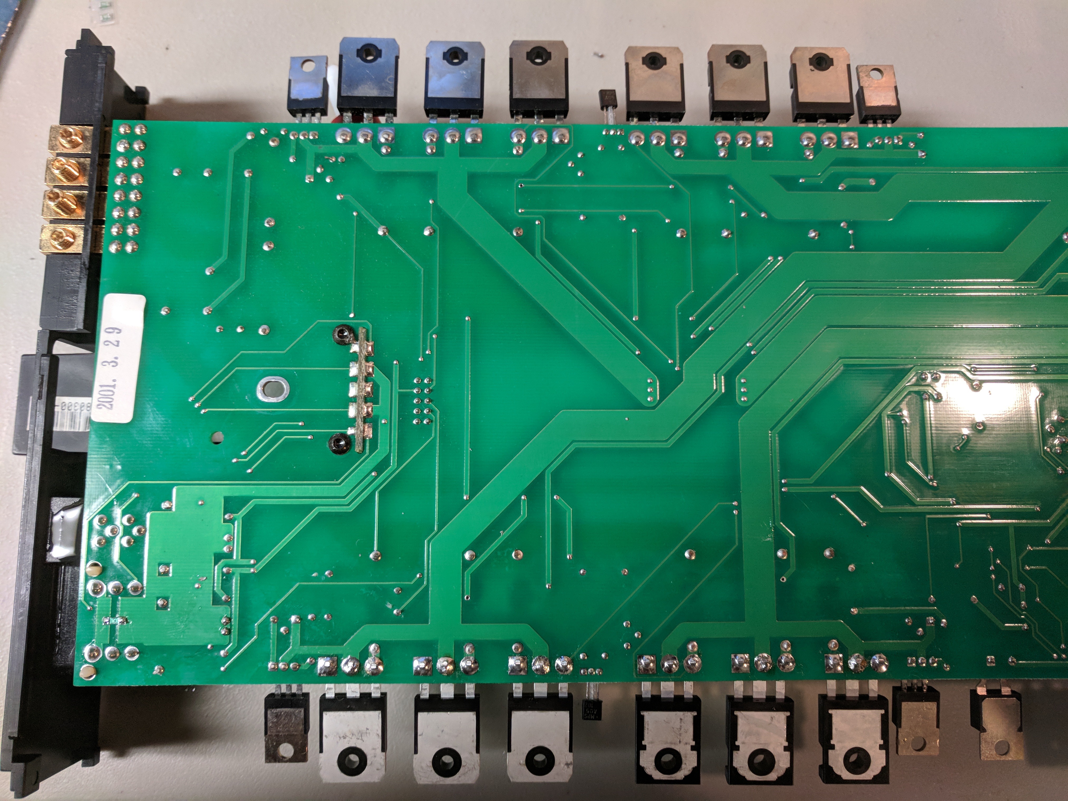
So this is what I was greeted to on the bottom side of the PCB
there was a glob of solder connecting a couple points on the capacitors above. You can see the wire globbed in to replace what I think was a fuse
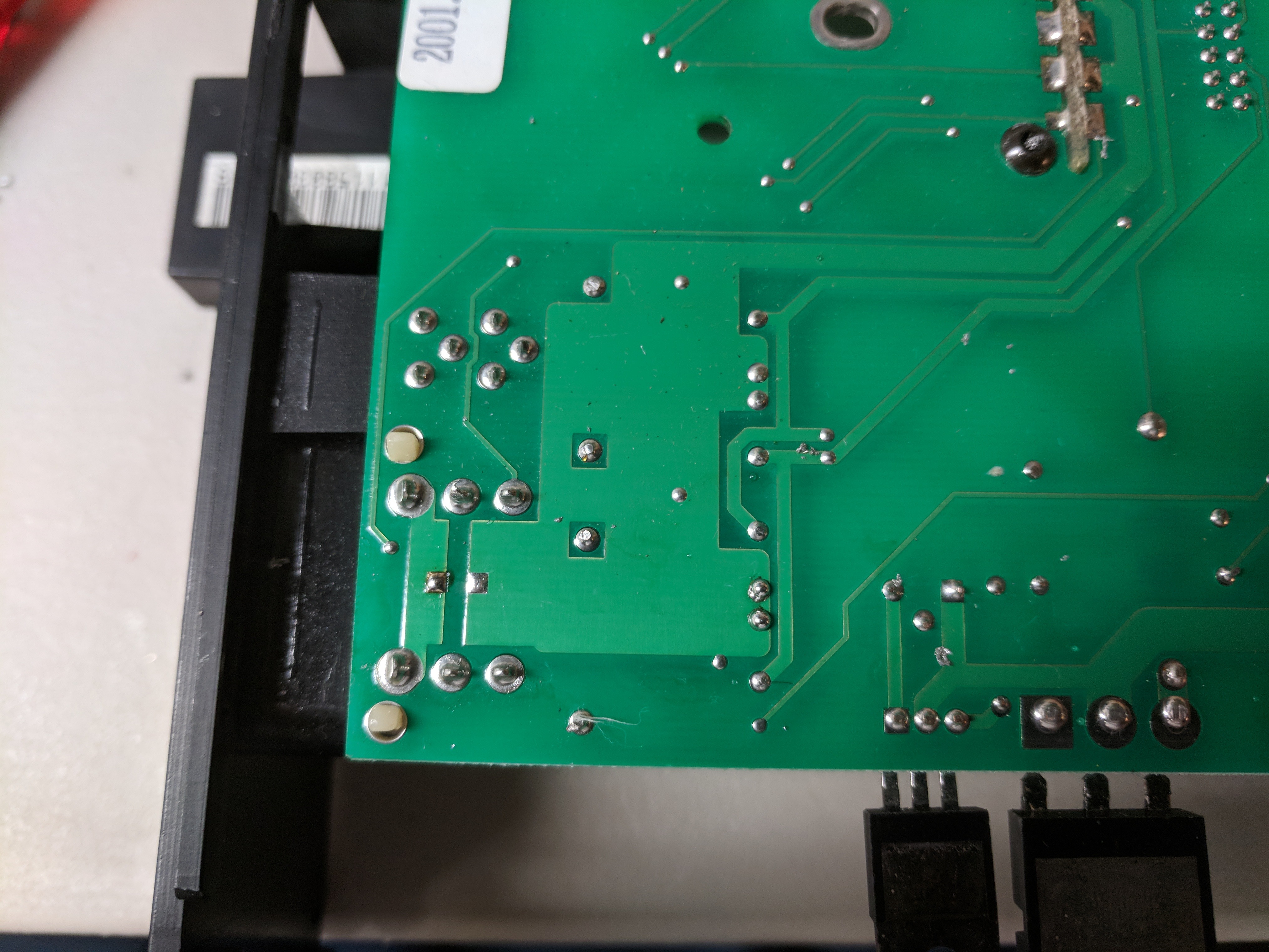
Cleaned up the mess, the solder glob was messy but harmless since they were on the same trace
This is where I think a fuse is supposed to go, on those pads
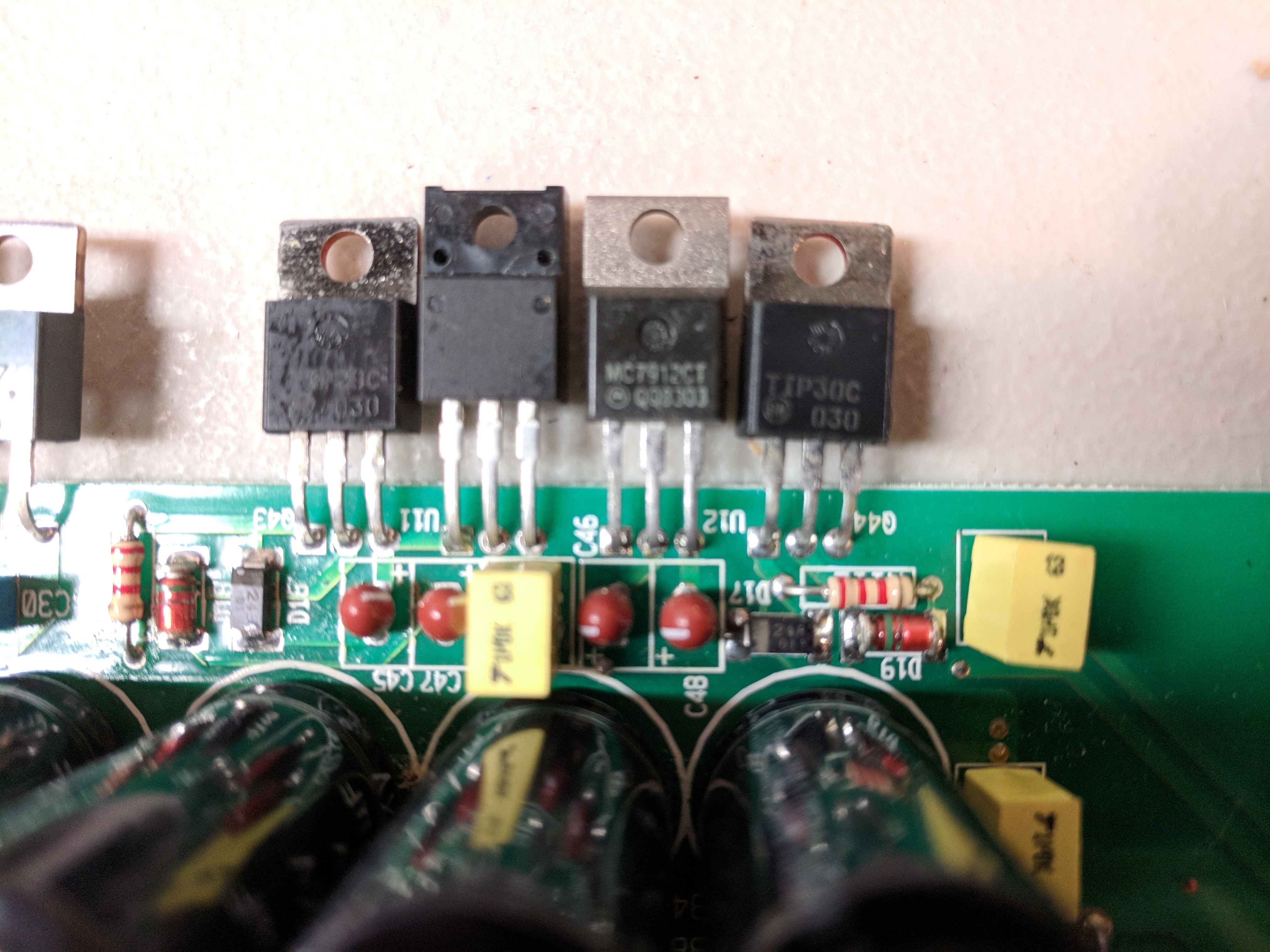
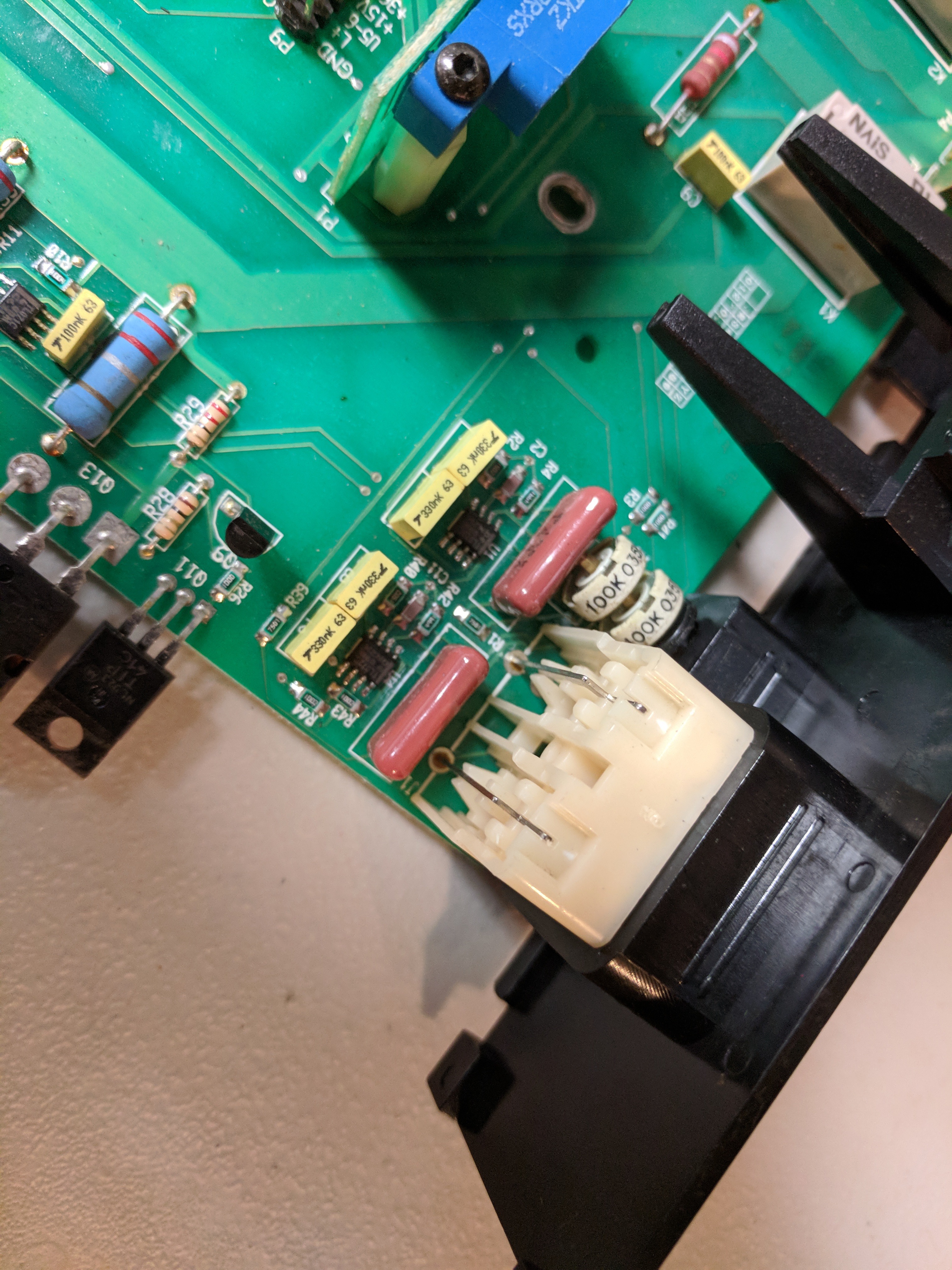
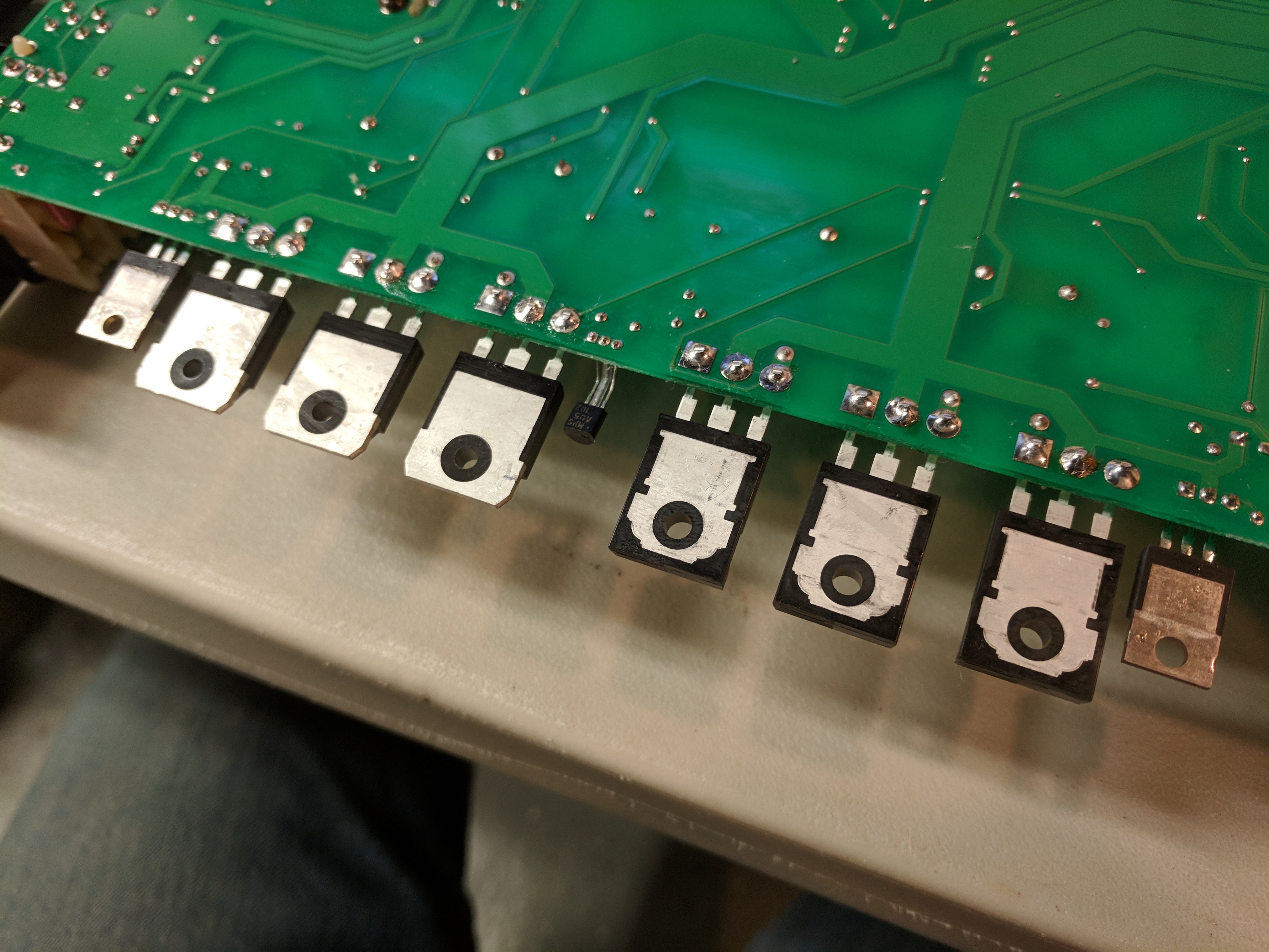
It appears as someone did work here, no idea if these are the original or even correct components
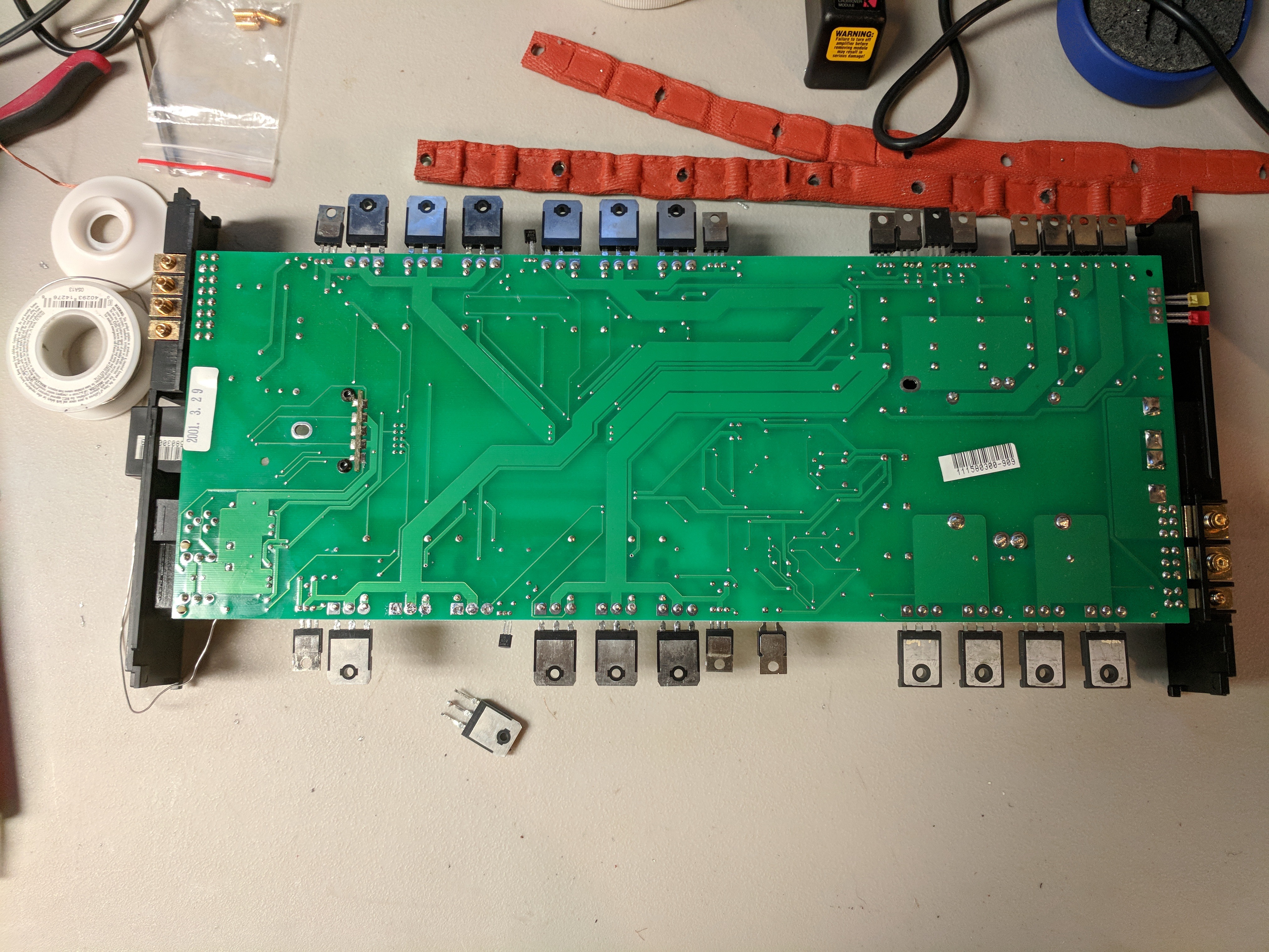
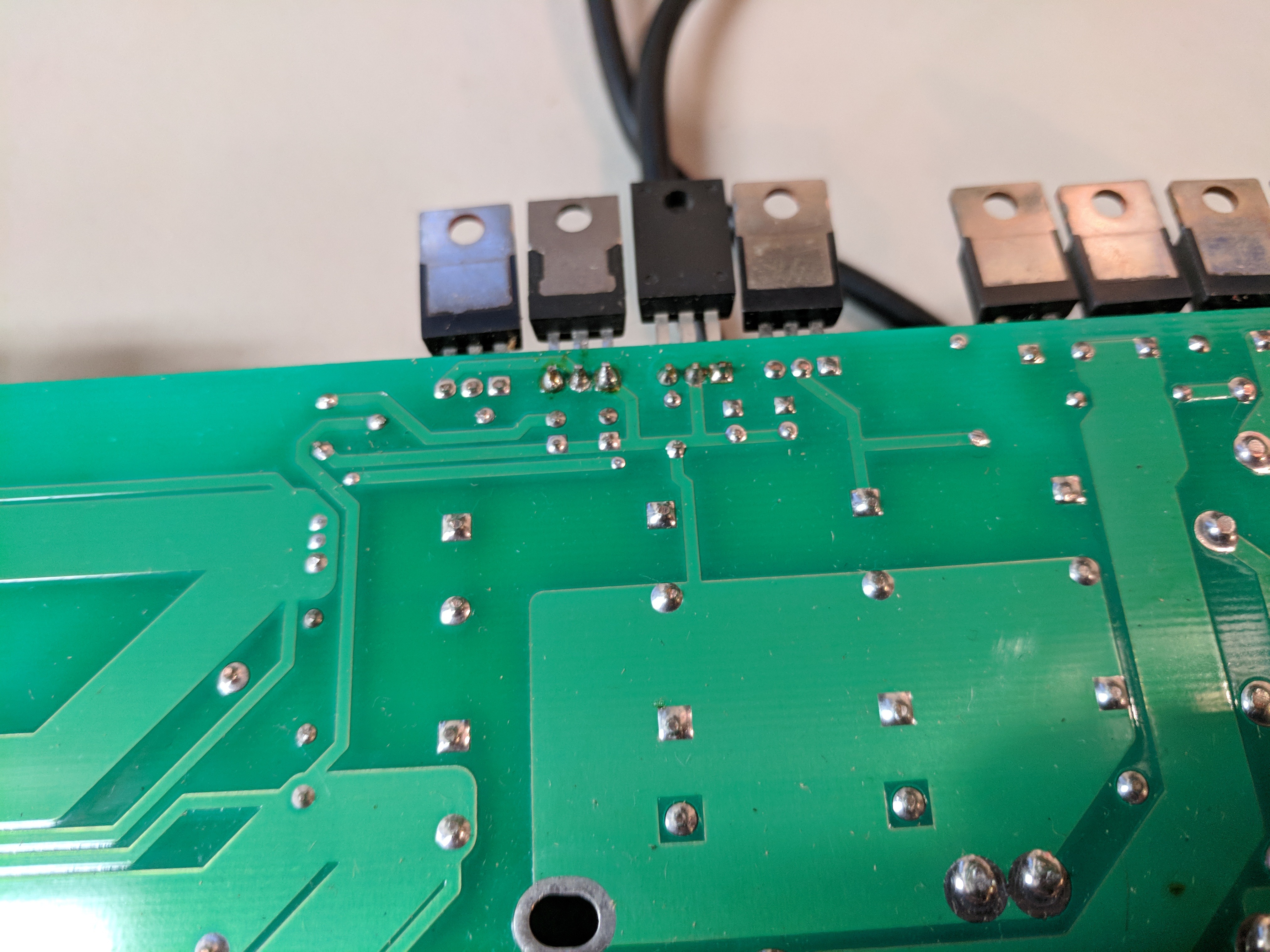
And just a overview of the board with 2 of the TIP35Cs removed. One is dead shorted.
So this is what I was greeted to on the bottom side of the PCB
there was a glob of solder connecting a couple points on the capacitors above. You can see the wire globbed in to replace what I think was a fuse
Cleaned up the mess, the solder glob was messy but harmless since they were on the same trace
This is where I think a fuse is supposed to go, on those pads
It appears as someone did work here, no idea if these are the original or even correct components
And just a overview of the board with 2 of the TIP35Cs removed. One is dead shorted.
I assume that it did in fact have one, otherwise it was a different type of component that someone fried and bypassed with that wire.
I was thinking it would be something in the 1 amp ballpark. Thank you
I was thinking it would be something in the 1 amp ballpark. Thank you
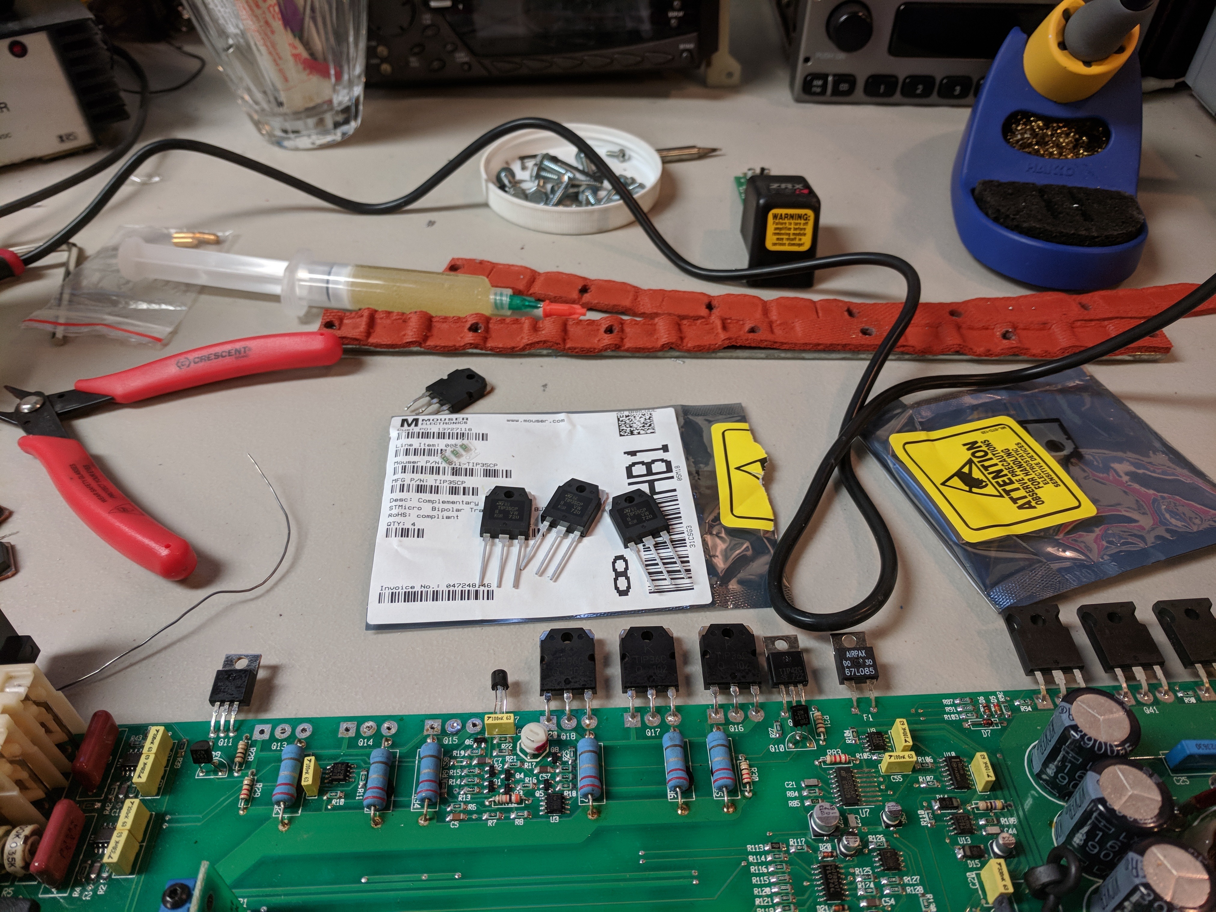
Getting ready to order up components.
Do I need to change the TIP36s tranisitors on the other rail or just the bank of TIP35s?
The resistors seem fine
Do I need to change the TIP36s tranisitors on the other rail or just the bank of TIP35s?
The resistors seem fine
In this amp, three of the TIP35s and three of the TIP36s make up one channel. I'd replace all outputs (six total) in the channel that failed.
Got all the parts on order from Mouser last night, I'll report back once I get them installed and see what happens. Thank you for the help so far!
I had one of the ZR amps way back, it had a smd fuse in the rca area. Can't remember what size it was but do remember thinking it was a good idea with all of the ground issues crappy amp installations cause.
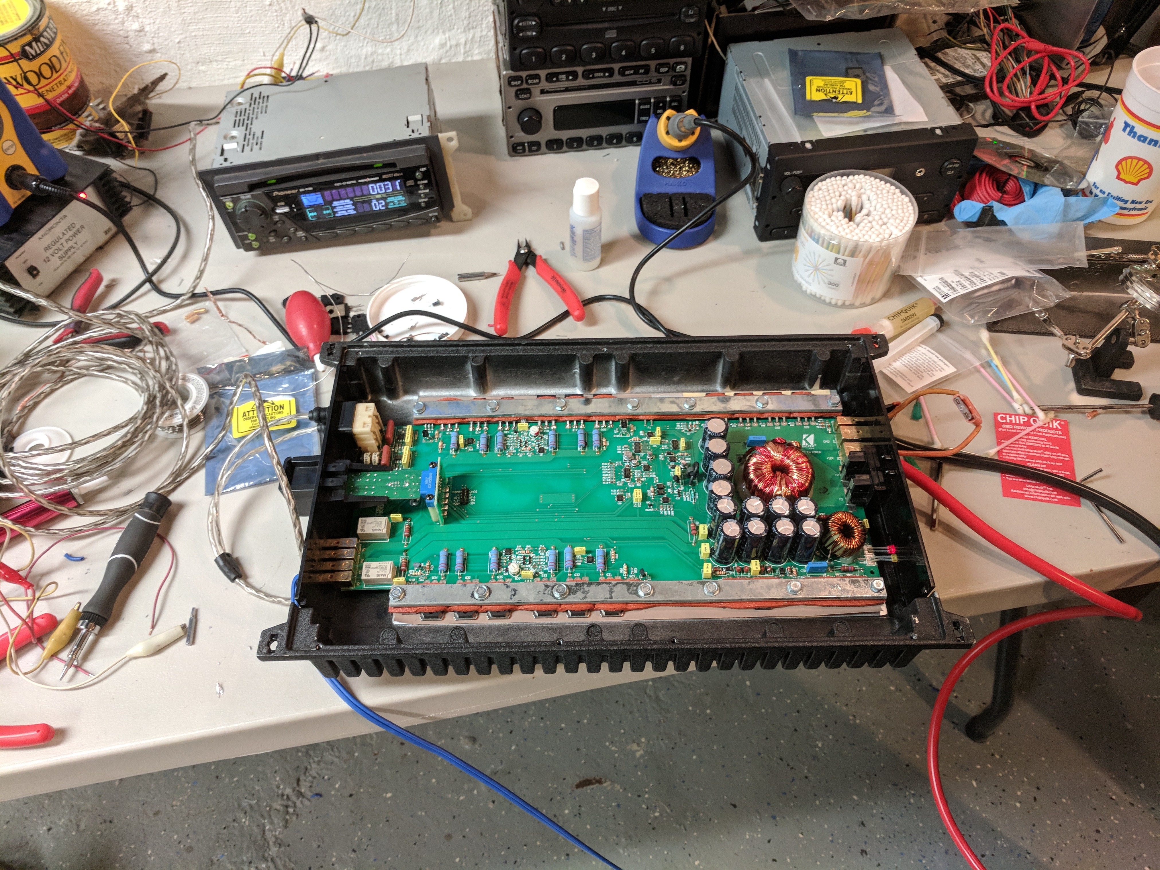
Ok, So I got all the parts in the mail today. Installed tonight.
I have to upload pictures soon. I'm pretty happy with how it turned out.
Happy to report that this amplifier is back alive.
Perhaps its because I have it on a car battery on the bench and a Head unit is being powered via a benchtop power supply, but this seems to have a odd hum to it even when nothing is being played. If I turn the gain almost as low as it goes it will mostly go away.
I tend to think this is because of how I have it setup right now, but if I'm wrong I'd rather repair while I still have it all accessible
Thanks. That did help. Though I think my bigger issue is that my benchtop power supply is just noisy. I should upgrade that sometime.
So it seems to be in good working order now. I massively appreciate the help.

So it seems to be in good working order now. I massively appreciate the help.
- Status
- Not open for further replies.
- Home
- General Interest
- Car Audio
- Trying to revive a Kicker ZR360