Hi
I need help troubleshooting the simples circuit ever.
Very load hum when driving an amp and test speakers.
I used a meter and scope, but don't know how to use a scope properly.
9v DC across bias resistor 2.2k.
Readings (no signal):
22v DC pre-regualtors
20v DC post-regulators
+- 1mV DC at output. It varies, not steady. It goes negative and positive.
Right:
D- .04v DC
G- 0v DC
S- 10.9v DC
Left:
D- .03v DC
G- 0v DC
S- 12.43v DC
The scope showed this pattern with a 1k computer generated sine wave. Probably not the cleanest waveform.
When turning up the volume pot, the sine became more like a sine wave, but it had take the form of smaller sines composing the larger sine wave.
Like a large single carrying a smaller signal.
Are we talking about the attached circuit?
Assuming we are, isn't your supply voltage too low then? What regulator are you using?
I'd guess that when the supply is 35V, the bias resistor should drop around 10V and that the drain should be maybe .5V over ground potential. As the gate is not biased it should sit at 0V, just like the AC-coupled output.
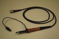
And concerning the scope: The tip of the probe is where you pick up the signal, the reference (ground) is usually the small alligator clip (or the shield of the BNC connector). But BEWARE, it's usually internally connected with earth-ground, so it is not floating (like your battery operated DMM)! If you f.e. would want to look at the signal across the bias resistor, and connect the tip and the clip over the resistor, you'd be grounding one side and most likely release some magic smoke. A scope is best used to read signal in reference to the circuit's ground.
For troubleshooting you usually inject a sinewave (1k, 1Vpp or so) in the circuit and look for the part of the circuit where it gets screwed up. The fault will often be close to this point. Square-waves are also highly useful.
And post some pics please!
Assuming we are, isn't your supply voltage too low then? What regulator are you using?
I'd guess that when the supply is 35V, the bias resistor should drop around 10V and that the drain should be maybe .5V over ground potential. As the gate is not biased it should sit at 0V, just like the AC-coupled output.
And concerning the scope: The tip of the probe is where you pick up the signal, the reference (ground) is usually the small alligator clip (or the shield of the BNC connector). But BEWARE, it's usually internally connected with earth-ground, so it is not floating (like your battery operated DMM)! If you f.e. would want to look at the signal across the bias resistor, and connect the tip and the clip over the resistor, you'd be grounding one side and most likely release some magic smoke. A scope is best used to read signal in reference to the circuit's ground.
For troubleshooting you usually inject a sinewave (1k, 1Vpp or so) in the circuit and look for the part of the circuit where it gets screwed up. The fault will often be close to this point. Square-waves are also highly useful.
And post some pics please!
Attachments

Hi Rodeoodave,
I'm using 19v, because I read 16v was suppose to be optimum, but 16v wasn't working. I'm starting in to think I made it up somehow.
Some of the stuff you said about using a scope went over my head in first reading.
Might just bump it up to 35v.
I'm using 19v, because I read 16v was suppose to be optimum, but 16v wasn't working. I'm starting in to think I made it up somehow.
Some of the stuff you said about using a scope went over my head in first reading.
Might just bump it up to 35v.
...
Some of the stuff you said about using a scope went over my head in first reading.
...
Maybe it was too fast, and certainly confusing.
Okay, what a scope does: It shows a time-resolved signal. A DMM doesn't do this, it it shows an averaged signal (DC or RMS-AC).
A DMM is usually battery operated, so the contacts of the probes are floating. This means that there is no fixed or defined potential between the probes and mother earth, they're just floating in mid-air. When you measure a voltage drop over a resistor, the measured potentials ideally don't get disturbed because they don't get pulled somewhere.
With a scope it's usually different. It's mains-powered, and older types have CRT displays and thus employ high voltages. For shielding and protection these scopes usually have a metal case which is connected to earth.
I like to distinguish between ground and earth-ground. Ground can be floating (=not having defined potential ), earth-ground is connected to mother earth (literally). A battery f.e. is floating: Between the poles there's say 1.5V, but no fixed potential to anywhere else. We usually call the minus-pole ground, and the plus-pole hot.
The same goes for a Galvanically isolated secondary of a transformer: The primary is usually connected to Live and Neutral. Live is referenced 110V or 240V (RMS) above/below Neutral, 60 or 50 times per second. Neutral is basically Earth, Earth itself is connected to the soil via a conductor. That's why you can touch N or E, but usually get zapped when you touch L while not being perfectly isolated from earth. Current will flow through you to mother earth (or the other way, depending on polarity). Once there is a Galvanic isolation, the secondary is floating again (assuming there's nothing connected to the secondary).
Now the important part: The DMM usually has two probes. When measuring voltages you can put the probes anywhere, you won't produce a short. Think of it as a 10M Ohm resistor you put over stuff (in parallel). You can put it anywhere, no excessive current will flow through it. (When measuring currents it's like putting a wire over stuff, that's why you should measure current in series with stuff).
Now it comes: A scope is usually different. It's like the DMM with two probes, but one is connected to earth! Try it, take your DMM in continuity tester mode and measure from the scope's BNC-connector to the earth-pin of it's power plug. It will likely go beep.
The way to NOT use a scope is to measure over components as you would do with a floating DMM. You will short out things and they will blow up.
The way to use a scope is to connect the ground of the scope with the circuit's ground, and then measure voltages with the tip (assuming you use a scope probe).
Your probe will look like to one attached. The alligator-clip is usually earth-ground, as is the shiny metal part and the outer part of the BNC-connector. With the shiny metal part you can easily short out stuff, so put heatshrink tubing over it. The tip is used to prod around.
When using a scope you should be aware of two things:
You earth-ground your circuit, potentially causing ground-loops resulting in hum.
When prodding around in live equipment, earth-connections are as dangerous as the present voltages. Why? Because they deliver a low-resistance path for currents. Touching a live wire while your other hand, elbow or pinky finger touches earth may result in a nasty current from one arm to the other.
Attachments
Last edited:
Should be:Right:
D- .04v DC
G- 0v DC
S- 10.9v DC
Left:
D- .03v DC
G- 0v DC
S- 12.43v DC
D ~ 10V
S ~ 0.5V
Have you turned those lovely SK170's the wrong way?
Rodeodve, thanks for taking the time to explain. I will sit down and try to make sense of your explainations.
I should have mentioned that I did not have the proper scope test leads. I had a couple of BNC to female RCA adaptors. I plugged in the output of the preamp to the female RCAs/BNCs of the scope. Sounds like maybe I should not have done it this way.
Even in my elementery thinking, I decided to use the scope for viewing the signal waveform only. I used the DMM to read voltage across components.
Yggdrasil,
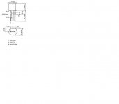
I don't think I have them reversed. I checked and re-checked this against the 2sk170's spec sheet.
Facing the flat part of the jfet: D G S. Is this correct?
Thanks,
Vince
I should have mentioned that I did not have the proper scope test leads. I had a couple of BNC to female RCA adaptors. I plugged in the output of the preamp to the female RCAs/BNCs of the scope. Sounds like maybe I should not have done it this way.
The way to NOT use a scope is to measure over components as you would do with a floating DMM. You will short out things and they will blow up
Even in my elementery thinking, I decided to use the scope for viewing the signal waveform only. I used the DMM to read voltage across components.
Have you turned those lovely SK170's the wrong way?
Yggdrasil,
I don't think I have them reversed. I checked and re-checked this against the 2sk170's spec sheet.
Facing the flat part of the jfet: D G S. Is this correct?
Thanks,
Vince
Attachments
Last edited:
Hi
22v DC pre-regualtors
20v DC post-regulators
I take this is the PSU regulator you've measured.
A drop of 2V over the regulator is not enough. You have most likely 50 or 100Hz hum, and that's from the PSU.
Try adjusting the regulator down to supply like 17V, and see how things change.
Magura 🙂
That won't be a problem because I have the adjust resistor set on test leads.
Got tired of soldering and de-soldering.
Will know later tonight.
thanks!
Got tired of soldering and de-soldering.
Will know later tonight.
thanks!
OK,
I am running the JFETBOZ with 14.05V rails - matched 2SK170BL's
All other resistor values exactly as Nelson posted on the 1st page of the JFETBOZ thread.
#1
D=2.02
G=0
S=57.4mV
#2
D=2.00
G=0
S=55.0mV
The psu is a RCRC with 0.47 3W power resistors and 2200 uF audio grade electrolytics
I am running the JFETBOZ with 14.05V rails - matched 2SK170BL's
All other resistor values exactly as Nelson posted on the 1st page of the JFETBOZ thread.
#1
D=2.02
G=0
S=57.4mV
#2
D=2.00
G=0
S=55.0mV
The psu is a RCRC with 0.47 3W power resistors and 2200 uF audio grade electrolytics
I only suggested that the Jfet's was turned around due to the suspicious voltages. I just reread the datasheet, but found it confusing.
A picture says more than thousand words, so I'll attach the pictures of a schematic and PCB I have used. PCB viewed from above.
A picture says more than thousand words, so I'll attach the pictures of a schematic and PCB I have used. PCB viewed from above.
Attachments
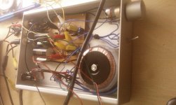
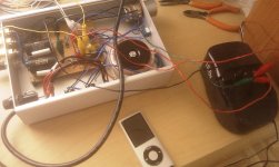
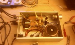
The circuit portion is fine. Running off a 18v cordless drill battary.
Sound good too. Playing thru a Gain Clone. Pot set to just past 9 o'clock and it sounds good and loud.
Might be the power regulators aren't filtered enough? Only using 1 uF after regulators. I used the spec sheet schematic example to build PS.
A few pics attached.
Vince
Sound good too. Playing thru a Gain Clone. Pot set to just past 9 o'clock and it sounds good and loud.
Might be the power regulators aren't filtered enough? Only using 1 uF after regulators. I used the spec sheet schematic example to build PS.
A few pics attached.
Vince
Attachments

YES! add a CRC filter - use 0.47ohm 3W resistors maybe 2 or 3 per bank in parallel and add some 2200uF Nichicon FG or KW for the "C" portion.
Lookin good...
I have been swapping in and out the JFETBOZ and my 5687 Aikido and they both have similar gain and sound...both very nice and warm.
I have been using both the Pass F5 and my SimpleSE running KT88's. The F5 definitely has more punch but there is something magical about a nice tube power amp. I figure the SimpleSE is running about 6W.
I got a chance to listen for some time with a set of TEAC mini-system speakers. It gave me the same impression the F5 did when playing thru these small test speakers. Big potential!
So you're saying place a CRC filter before the regulator or after? Before would be easier.
So you're saying place a CRC filter before the regulator or after? Before would be easier.
Just an FYI-
Haven't had a chance to play around with the PS, but I did switch out the standard VCR test cables (non-75 ohm type) for lower-end Audio Quest RCAs and there was a noticable improvement to an already nice sounding preamp. More information seemed to pass through.
Didn't know what to expect, but I'm impressed.
An Improvement
As a test, I placed a 2200 uF cap in front of the regulator and it did filter most of the noise. It's still noisy, like a tube guitar amp, with ear at the speaker. A nice benefit of the filtering is that the voltage adjust resistor is actually now bringing the voltage closer to the calculated voltage.
Will try to place the CRC filter after the regulator and see what I get.
Thanks,
Vince
Attachments
A drop of 2V over the regulator is not enough. You have most likely 50 or 100Hz hum, and that's from the PSU.
Try adjusting the regulator down to supply like 17V, and see how things change.
Either you should fix the regulator, or ditch it entirely.
What you have there is a C filter, with some redundant stuff added to it.
Magura 🙂
Try adjusting the regulator down to supply like 17V, and see how things change.
Either you should fix the regulator, or ditch it entirely.
What you have there is a C filter, with some redundant stuff added to it.
Magura 🙂
It's just under 17v at around 16.75v.
Been thinking about ditching it entirely. Don't think any regulator can touch th battary supply. It sounded great.
Either you should fix the regulator, or ditch it entirely.
Been thinking about ditching it entirely. Don't think any regulator can touch th battary supply. It sounded great.
An Update
Installed a 2200/.47/2200 CRC filter after the regulator circuit. This had some effect on the hum. Then installed a 220uF electolytic across the pos/neg regulator supply inputs before the regulator. This had a significant impact on lowering noise and hum. Have to place my ear against the speaker to hear hum and noise. Some of this buzz might also be due to the Gainclone amp.
Will probably install 2200uF caps, instead of 220uF.
Would it be helpful to install an AC cap across the bridges and AC line?
Thanks for your help. The preamp sounds great!
Vince
- Status
- Not open for further replies.
- Home
- Amplifiers
- Pass Labs
- Troulbleshooting BOZ-J