Pascal SPRO2 module - no sound, update: In protect mode
Hi guys,
I have got a RCF Subwoofer 905-ASII with no output. The subwoofer has got the pascal Spro2 module. I understand that there aren't any available service manual/schematics for the module. I couldn't find any obvious faults like shorted FETs etc.
I have ruled out the input/dsp board which is made from RCF by plugging that into a working subwoofer.
Any ideas on what to look for? I have a feeling the it might be that the mute signal is on. I couldn't find a testpoint to test it, and I couldn't find the pinout for the 26 connector either.
Your help would be greatly appreciated 🙂
Last edited:
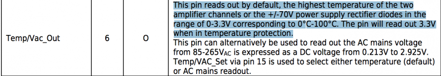
Digging up shelved projects. It seems that the module is in protect mode when measuring pin 6 'Temp out pin' I first read values which was going up and down. Anyway after further troubleshooting it seems that the RCF sub's micro controller is designed to toggle between Temp and VAC select pin 15.
I bypassed the toggling signal and manually selected what to monitor. When I short pin 15 to ground (VAC monitor) on pin 6 I get a good reading of around 0.16V. When I leave pin 15 open (Temp monitor) I read 3.3V which would be registered as a fault and the amp remains in protect mode.
I'm not inputting any signal. Anyone have any idea how the temperature is measured in the module and on which PASCAL ic pin is the temperature measurement inputted?
Thanks
The connector pinout and some of the descriptions that have for some reason been omitted from the S-Pro DS are actually in the U-Pro datasheet. If you haven't read that, start there maybe?
Thanks so much for the info, I downloaded the datasheet and got some helpful hints I believe. Its worded in a mysterious way though hehehehe...The connector pinout and some of the descriptions that have for some reason been omitted from the S-Pro DS are actually in the U-Pro datasheet. If you haven't read that, start there maybe?
Attachments
What do you get on pin 11? From your explanation I agree that it sounds like you are getting the temp. protection signal, but it seems a bit weird if the module is cold. Does pin 11 show that the amp is in protection and what do you get if you measure the voltages of the AUX PSUs from pin 18-26?
Pin 11 remains to be held low.What do you get on pin 11? From your explanation I agree that it sounds like you are getting the temp. protection signal, but it seems a bit weird if the module is cold. Does pin 11 show that the amp is in protection and what do you get if you measure the voltages of the AUX PSUs from pin 18-26?
With AUX PSU pins =
+15V == measures around 14.7V
-15V == measures around - 14.8V
+7.5 == measures around 7.5V
They seem stable and ok.
I didn't measure pins 7&8 they are Vout Monitors for +-70V rail because in the application notes it says =
"This pin reads out the amplifier channel 1 output voltage. The signal will be in the range ±10Vp corresponding to ±70Vp on the output of the amplifier. The signal is high impedance and requires a buffer if used."
I wasn't sure about the high impedance and requires buffer part so I didn't want to take a chance probing around - would be great if you could shed some light on this 🙂.
I also should add, I am not playing any signal through and I do not have a load connected at the moment. I understand that there is a 'wake up' feature with music signal in these modules but still a temp protection shouldn't be there right?
The reason I don't have a load connected is I have forgotten how the speaker was connected, whether in BTL or SE mode I guess I could figure that out from pin 14 whether its left open or shorted to ground.
Any ideas on how to proceed further?
Really do appreciate the help.