I bought a GFA-555 mk1 that had a little higher dc offset than I liked (~75mv) and I wanted to add speaker protection boards (https://www.diyaudio.com/forums/gro...n-rtr-ssr-dc-speaker-protection-delay-gb.html). My amp had a very early version of the boards (no silk-screening) and would not work well with modern transistor pinouts. I decided to go with Hoppe's board and ordered all parts from mouser. I got it all soldered up and carelessly plugged it in. The right channel went up in sparks. After some troubleshooting with Chris @Hoppe's Brain, he determined that the output transistors blew. I replaced all 4 of them with his suggested part, replaced the blown resistors, and tested all the components in circuit against the left channel. I had also added bypass caps to the output stages but removed those capacitors to narrow variables. Everything is reading the same across channels. I purchased a variac so that I could avoid catastrophe the second time. The results are better(?) but still concerning. The amp seems stable to 125v but there is a loud, concerning hum that starts right around 95v. The protection boards are supposed to tap power off the B+ rail but I am not reading anything near 81v+. I've not attempted to run audio through it.
Components are exclusively from Mouser and should be genuine. I've done a few homebrew electrical projects and feel good about my soldering.
Appreciate the help. Attached some photos in case there are obvious wiring mistakes.
Components are exclusively from Mouser and should be genuine. I've done a few homebrew electrical projects and feel good about my soldering.
Appreciate the help. Attached some photos in case there are obvious wiring mistakes.
An externally hosted image should be here but it was not working when we last tested it.
An externally hosted image should be here but it was not working when we last tested it.
An externally hosted image should be here but it was not working when we last tested it.
An externally hosted image should be here but it was not working when we last tested it.
Attachments
Hey there, Chris Hoppe here!
Are you seeing an excessive current draw as you turn up the variac? Any DC offset appearing on the output?
You might have bad filter capacitors. It looks like you have the TOWA capacitors, and some of these are only rated at 80V for an 83V rail, and do go bad occasionally. The later models used 100V capacitors and those rarely go bad. You can measure AC ripple voltage across the capacitors, and it should be similar to the working channel.
Are you sending the feedback signal to the board before or after the protection board? It would be a problem if the feedback signal was being switched on and off by the protection board. Whatever you do, that feedback line should always be connected to the output.
It looks like you have the zobel ground going to the protection board. (SPK GND terminal) It should really be going straight to the star-ground, or the negative binding post, but I doubt that's your problem.
You might want to clean up the board with alcohol and a brush, you might have a little scrap of metal or a solder ball bridging a contact somewhere it shouldn't.
The board you have there is actually meant for the later production run 555's. There are only two differences; The brackets that hold the board in place are longer in the old ones, and the bridge switch is different. (Which is why yours doesn't fit quite right.) Make sure your mounting bracket isn't making electrical contact with anything underneath the board.
I do actually sell a version of the board specifically for these models.
Hoppe's Brain BFA-555 for early rack-mount models
If you want to try again and build a new board from scratch, you can have one for the price of shipping, plus $20 because this type of board also includes RCA jacks and a mounting plate to fit over the oval hole in the back panel. But I would need you to send me proof that you've destroyed the old one... drill holes in it and send me a picture or something.
Maybe simplify your troubleshooting, and take the protection boards out of the circuit until the amp is working.
Thanks for your help. I'm going to follow your advice and do a little more troubleshooting before I take you up on the offer. I've not run sound so I can't confirm that I have a working channel. I'll refer to them as smokey and non-smokey since I only know that one went up in smoke. I removed the fuses from either and both channels and the hum seems to happen regardless. Maybe there is a short somewhere?
Not sure on current draw. I plan to go get a kill-a-watt soon. There were no changes in dc offset to the outputs. It showed about -.03v all the way up to 125vac
I don't have a scope but used my multimeter to check ac across the big capacitors. The non-smokey channel measured .0073v and .0086v. The smokey channel measured .0090v and .0137v. Is this difference problematic?
I removed the protection boards and wired in jumpers so that the signal paths match the original layout. It did not seem to make a difference. Thanks for this note. I'll make sure to change the wiring when I'm reinstalling the protection boards.
I noticed that the brackets were getting close and had used some silicone pads to insulate them. I removed the brackets completely and used some electrical tape to suspend the board while testing. I gave the board a scrub with a toothbrush and some IPA. No easy fix unfortunately.
Did I reconnect the bridge rectifiers correctly (see pics)? I take pics as I go to reference but I'm trying to rule out a stupid mistake.
Thanks
Not sure on current draw. I plan to go get a kill-a-watt soon. There were no changes in dc offset to the outputs. It showed about -.03v all the way up to 125vac
I don't have a scope but used my multimeter to check ac across the big capacitors. The non-smokey channel measured .0073v and .0086v. The smokey channel measured .0090v and .0137v. Is this difference problematic?
I removed the protection boards and wired in jumpers so that the signal paths match the original layout. It did not seem to make a difference. Thanks for this note. I'll make sure to change the wiring when I'm reinstalling the protection boards.
I noticed that the brackets were getting close and had used some silicone pads to insulate them. I removed the brackets completely and used some electrical tape to suspend the board while testing. I gave the board a scrub with a toothbrush and some IPA. No easy fix unfortunately.
Did I reconnect the bridge rectifiers correctly (see pics)? I take pics as I go to reference but I'm trying to rule out a stupid mistake.
An externally hosted image should be here but it was not working when we last tested it.
An externally hosted image should be here but it was not working when we last tested it.
Thanks
Tested the bridge rectifiers and they behave as expected. The hum remained the same with the rectifiers disconnected. The only thing connected is the toroidal transformer. I tried tightening down the nut but it didn't make a difference. Read that DC in the line could cause humming. I measured my variac and there is about 13mVdc. Is this enough to cause loud humming? I've not been brave enough to plug the amp directly into the wall since the first fireworks show.
Is there a recommended repair process or replacement?
Is there a recommended repair process or replacement?
I'm a bit unsure about the bias compensation in these amps from looking at the circuits. Was the bias set correctly? Both over and under-bias can have issues (under can lead to instability).
Reconnected one channel (no protection boards) and set the bias following the service manual. There's about 30mVdc at the outputs.
No noticeable change in transformer buzz/hum.
I took some measurements at B+, V+, and D+ and did not get what I was expecting.
v+/-=+/-81V
B+/-=+/-.54V
D+/-=+/-1.1V
The schematic led me to believe B+ should be 81V
I also played some audio through the channel and monitored AC at the outputs. Signal is detected and the distortion lights did not come on.
Hummm. If you've got a hum with only the power transformer connected, then I guess you have a bad power transformer! That's pretty rare. I've only seen one bad GFA-555 transformer.
DC offset on your line would only cause a small hum, and you're reading very little offset there anyway. North of 1V is a problem.
Your readings on V, B and D are all normal. B+ and B- are deceptively named. It's not the supply voltage, and should be around 0.6V.
Also the AC ripple on the filter caps seems normal too. DC offset of 30mV is A-OK. It sounds to me like the amp part is working fine.
With the secondary not connected to anything, do you read any resistance between primary and secondary?
If you need a new transformer, I think this one will fit the bill, (800VA, 55+55V) though I haven't tried it, and it's a bit hard to be sure of the exact rail voltage you'd end up with, but I think you'd be somewhere around 83V. If it's too high, you could exchange it for the 50V version.
https://www.parts-express.com/avel-lindberg-y236904-800va-55v-55v-toroidal-transformer--122-715
I once did a dual-mono conversion on a 555, using two Triad 50V 500VA transformers, and that ended up with a rail voltage around 75V, which is lower than the stock 83V, but this was intentional, to compensate for the increased total VA of the two transformers. (1000VA versus the stock 850VA) The resulting amp had slightly lower 8 ohm power but more 4 ohm power. It sounded amazing.
A custom super-high-current GFA-555 Dual-mono upgrade | Hoppe's Brain
Thanks for this help. I can confirm that the transformer vibrates when powered alone. I suspended it out of the chassis and while the noise went down, the vibration was still audible (and I could feel it). There is OL between primary and secondary. I'll look in to replacing the transformer.
2 followups:
1. Since the board seems good, does it make sense to redo it with the revised version? I managed to mount the one I have seemingly well and can use the silicone pads to isolate the brackets.
2. I added an IEC connector but did not wire the earth to chassis. I've seen this mod done fairly often but also read that it can cause feedback issues in older gear that was not designed with the additional prong. Can I wire the earth pin to the chassis?
Cool! Sounds like you found the issue. Too bad it's a bit expensive. Oh well, the new transformer will be really nice.
1. Nah, if you're OK with how the bridge switch is installed, you can save yourself the work of re-doing the board. There's no electrical difference whatsoever. The board is just shaped slightly different.
But if you want to install nicer RCA jacks, the offer stands for the adapter plate and RCA jacks.


I presume you have the oval hole left in the back panel, like this.

2. Yes absolutely, and I highly recommend connecting earth straight to the chassis. You won't get feedback, but you might get noise from a ground loop, especially if you have other components in your system that also have chassis earth connections. However, this is a non-issue if you use an earth loop breaker. A small resistance is placed between the amp's star-ground and the chassis, instead of tying the star ground straight to the chassis as stock. Rod Elliot wrote an excellent article on the subject.
Earthing Your Hi-Fi
You can build one by simply bolting an old 35A bridge rectifier to the chassis, and mounting the resistor and cap to its terminals.
1. Nah, if you're OK with how the bridge switch is installed, you can save yourself the work of re-doing the board. There's no electrical difference whatsoever. The board is just shaped slightly different.
But if you want to install nicer RCA jacks, the offer stands for the adapter plate and RCA jacks.
I presume you have the oval hole left in the back panel, like this.
2. Yes absolutely, and I highly recommend connecting earth straight to the chassis. You won't get feedback, but you might get noise from a ground loop, especially if you have other components in your system that also have chassis earth connections. However, this is a non-issue if you use an earth loop breaker. A small resistance is placed between the amp's star-ground and the chassis, instead of tying the star ground straight to the chassis as stock. Rod Elliot wrote an excellent article on the subject.
Earthing Your Hi-Fi
You can build one by simply bolting an old 35A bridge rectifier to the chassis, and mounting the resistor and cap to its terminals.
One more check before I order. I measured the bridge(?) where the primaries are attached for resistance. I expected most values but want to confirm the values in grey are correct. I numbered the tabs 1 (N) to 9(power switch).
Thanks
Thanks
Attachments
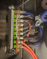
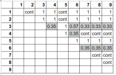
Yeah that doesn't mean much. You're measuring the resistance of the primary coils, and at those low ohm ranges, your meter's leads are going to have nearly the same resistance as the coils. But all of that looks pretty normal.
More importantly, you'll need to figure out where to connect the dual 120V primaries of the new transformer. Determine which terminals have hot and neutral connected.
More importantly, you'll need to figure out where to connect the dual 120V primaries of the new transformer. Determine which terminals have hot and neutral connected.
Thanks for all the help. Just placed the order for the transformer. I'll be back with photos when it arrives (and probably new questions)
The transformer delivery has been pushed twice and now has an ETA of mid September.
Would this be a good option?
750VA, 60V+60V https://www.newark.com/hammond/1182q60/transformer-toroid-120v-750va/dp/54X7542
Any other alternatives?
Thanks
Would this be a good option?
750VA, 60V+60V https://www.newark.com/hammond/1182q60/transformer-toroid-120v-750va/dp/54X7542
Any other alternatives?
Thanks
Last edited:
Yeah, the 48V Hammond should work! You might get slightly lower rails and a little less 8 ohm power, but better 4 ohm power, due to less rail sag. That's good for sound. The 60V one would probably give you 90V rails, too high. The 60V rating is at rated current and it's quite a bit higher with no load.
Ordered the 48v Hammond from mouser. In the meantime, this came up on CL locally: Power Toroidal Transformer for Audio Amp & CNC 230 AC 80 90 DC...
Did some searching and found. This thread What Toroid in Mackie M1400 and I looked at the schematic for the m1400. Don't see a VA rating but the thread does mention modding and Adcom. Thoughts?
Did some searching and found. This thread What Toroid in Mackie M1400 and I looked at the schematic for the m1400. Don't see a VA rating but the thread does mention modding and Adcom. Thoughts?
- Home
- Amplifiers
- Solid State
- Troubleshoot GFA-555 mk1 hum