Hello people,
I'm working on basic LM317 linear supply and I'd like to output three different voltages:
V+/V- for the audio circuit and an extra V+ for LEDs, relays, etc...
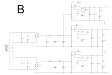
Which of the two following diagrams would you recommend in terms of isolation, performance, etc?
Ideally, I'd like to use (B) as it's a simpler solution but I'd really appreciate your input!
I'm working on basic LM317 linear supply and I'd like to output three different voltages:
V+/V- for the audio circuit and an extra V+ for LEDs, relays, etc...
Which of the two following diagrams would you recommend in terms of isolation, performance, etc?
Ideally, I'd like to use (B) as it's a simpler solution but I'd really appreciate your input!
Attachments
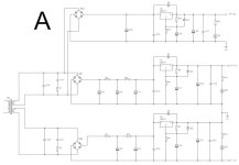
A but dependent of the loads and so preferably with separate windings, CLC filtering and better SMD regulators including a negative regulator. Or visit the perpetual thread of die/no/denoiser in all its seemingly never finished versions for improved LM317/337 circuits. For maximum loads of a few hundred mA there are many low part count excellent ultra low noise uLDOs available.
Also RF filtering is meanwhile necessary. I use ferrite beads for that in CLC at outputs and locally in circuits. Some are against that but having RF in circuits is IMHO worse than the beads.
For LEDs, relays it would certainly pay off to pick an uLDO (even a noisy one) and have less heat/losses. The less difference between transformer and regulator voltage the better. For instance 5V AC, 5V LDO and 5V relays.
It would help to mention the exact loads and necessary currents.
Last edited:
I would use not only LM317, but one LM337. Beside from that, you design a regulated PS for a purpose. Maybe explain?
If you want to improve it, you can spice these regulators with an opamp.
If you want to switch relais and this is for audio, keep transformer winding separate as jean-paul wrote. Also think about better filtering, there is serious noise comming from the mains.
If you want to improve it, you can spice these regulators with an opamp.
If you want to switch relais and this is for audio, keep transformer winding separate as jean-paul wrote. Also think about better filtering, there is serious noise comming from the mains.
Thank you guys.
The voltages I'm after are +/-30V and +24V. The transformer is a 2x30V (60VAC) and I'd very much rather having two secondaries instead of three. I'm not sure about the exact load yet but probably around 600mA or so.
1) That's probably a bit naive question but do the relais generate noise only while switching or they constantly pollute the supply. Same for the LEDs, do they inject noise only while they change state?
2) Why should I use a 337? I had the impression that it's better to use 317 since they are less noisy.
3) Can you recommend what extra filtering should I add? Are we talking about all three rails here or just for the 24V? My understanding is that both the realais and LEDs don't need particularly clean DC. I would think that even only some smoothing (without any regulation) would do the job if I wanted to go cheap.
4) RF filtering is provided from the IEC inlet. Is it not sufficient?
No time right now but please consider the consequences of the influence of solar and wind energy on the grid voltage and what that does do your secondary voltages. Unregulated was never an issue for relays and such but maybe it is now. No worries with just a 3 pin uLDO.
LM317/337 are not as low noise (without added trickery) as many recent uLDO regulators. If noise is your concern avoid LM317/337 alltogether.
600 mA in total or per branche? Normally one designs the PSU for its specific load.
LM317/337 are not as low noise (without added trickery) as many recent uLDO regulators. If noise is your concern avoid LM317/337 alltogether.
600 mA in total or per branche? Normally one designs the PSU for its specific load.
I'm not sure what do you mean with the uLDO. Do you mean in series after a 337?
The 600mA is a ballpark. The plan is to use this external supply with different devices (similar topology) ranging from 150ish mA to 600mA tops. This is the total load, not pair rail.
The 600mA is a ballpark. The plan is to use this external supply with different devices (similar topology) ranging from 150ish mA to 600mA tops. This is the total load, not pair rail.
It may be more optimal to design a few versions depending on specific demand as one size fits all generally does not work out that well.
Also the choice for classic high dropout voltage regulators will lead to heat and necessary heatsinks. The less voltage you need to drop the less energy is converted to useless heat and the smaller the PCB can be.
I would start by determining the current demand per branche and double the number as a design parameter. Then what ripple voltage is allowed. Ending with which regulator to choose and then the right transformer.
Last edited:

I'll choose A simply bcs it has one more cap on the input to isolate the load. relay won't generate noise, it's just an inductor.
thank you for your replies. I found some time to come back to this.
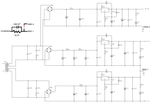
Considering the following schematic, GND 1 should be connected to PE at some point. The question is whether I should also connect GND 2 to this point? I believe the answer is "yes indeed" but as always any advice is welcome.
FWIW, GND1 is the "audio. ground" while GND2 is the "dirty ground" for lack of better terms.
Attachments

Don’t connect GND to PE directly.
PE is connected directly to a metal casing and is officially only for safety. GND is at the secondary side of PSUs. You may want it referenced to PE but not more than that. Unless you like hum and ground loops.
Never connect GND to a casing. Also never use casing as a conductor for GND. Casing is PE.
Where should I connect the GND then? Usually I connect GND and PE via a 10R // 100nF. Is this wrong practise?
That is OK of you mean you connect GND to PE with 10 Ohm 2W//100 nF. Floating is also a possibility but boobood in the english hemisphere. There direct connection of GND with PE in every device and hum/groundloops to solve are common.
Why? Because in theory an L mains wire could touch the secundary circuit (since the casing is connected to PE all is good).
Why? Because in theory an L mains wire could touch the secundary circuit (since the casing is connected to PE all is good).
Last edited:
Just either 1 of both as GND1 and GND2 will meet eachother at the load. You could choose the one that has highest load.
OK thanks. Just to clarify. You recommend that if for example GND 1 has the highest load, to connect only GND1 to PE and not both GND1 and GND2, right?
I'm asking because I'm not sure what you mean by "both as GND1 and GND2 will meet eachother at the load."
GND1 is for audio only while GND2 is for LEDs and relays only so, they don't really meet each other anywhere.
I'm asking because I'm not sure what you mean by "both as GND1 and GND2 will meet eachother at the load."
GND1 is for audio only while GND2 is for LEDs and relays only so, they don't really meet each other anywhere.
- Home
- Amplifiers
- Power Supplies
- Triple output linear supply