Just acquired an Acer PalmPro 7756PA DLP projector. Bought it as is for AU$20.
Had / has a burnt out globe. The lamp sled is the right one but the reflector & globe were as far as I can discover from a search reveals that the reflector is from a 3M MP7730 or a Mitsubishi SD10. The lamp was DC this projector takes an AC .
What I would like to do is bypass the lamp detect circuit to see if the projector is operational before spending money on a lamp. Have not been able to find a wiring schematic for this projector. Can anyone point me in the direction to find it?
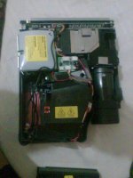
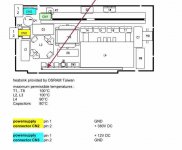
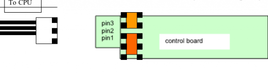
Here is the general layout of 7765PA
OOPS imaages in PDF, can't see to imbed images in post
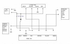
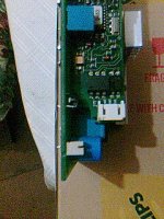
From CPU to sub board 6 wires. Seems to me only lamp door sensor & overheat sensor, no lamp sense
From Power supply to ballast two inputs 12 VDC & 380 VDC
From CPU to Ballast 3 wire
This comes from http://support.mpccorp.com/tech_support/CsmrEltrncs/Projectors/7004580/SpecVIPR150P16L_draft.pdf
Lamp is different 150/P24 but this correct ballast
Ballast at present not in projector.
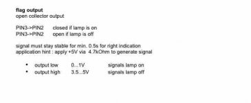
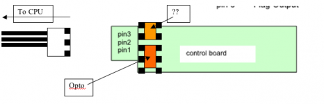
IF I short pin 3 to ground will it trick projector into thinking lamp is on??
OR do I need the ballast in for colour wheel synchronizing ??
There is another sensor to the side of the colour wheel, has 3 wires that go to CPU. Might this be a lamp on sense? Os something to do with the colour wheel? The colour wheel stepper motor is driven by its own ribbon cable.
Any help really appreciated
Had / has a burnt out globe. The lamp sled is the right one but the reflector & globe were as far as I can discover from a search reveals that the reflector is from a 3M MP7730 or a Mitsubishi SD10. The lamp was DC this projector takes an AC .
What I would like to do is bypass the lamp detect circuit to see if the projector is operational before spending money on a lamp. Have not been able to find a wiring schematic for this projector. Can anyone point me in the direction to find it?
Here is the general layout of 7765PA
OOPS imaages in PDF, can't see to imbed images in post
From CPU to sub board 6 wires. Seems to me only lamp door sensor & overheat sensor, no lamp sense
From Power supply to ballast two inputs 12 VDC & 380 VDC
From CPU to Ballast 3 wire
This comes from http://support.mpccorp.com/tech_support/CsmrEltrncs/Projectors/7004580/SpecVIPR150P16L_draft.pdf
Lamp is different 150/P24 but this correct ballast
Ballast at present not in projector.
IF I short pin 3 to ground will it trick projector into thinking lamp is on??
OR do I need the ballast in for colour wheel synchronizing ??
There is another sensor to the side of the colour wheel, has 3 wires that go to CPU. Might this be a lamp on sense? Os something to do with the colour wheel? The colour wheel stepper motor is driven by its own ribbon cable.
Any help really appreciated
Attachments
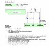
ywh said:sorry my poor english
Thanks YWH
My ballast is slightly different, not sure which points you mean to short.
Would prefer at this stage not to go near ballast with soldering iron.
Also would prefer not to have ballast in projector, if possible for initial tests.
Do you think shorting pins 2& 3 to CPU would do the same thing as your suggesting
thanks Dave
Attachments
Tried shorting pins from ballast to CPU didn't work.
Did manage to find schematic for projector, too big to attach (2.9MB), anyone want to look at a copy email me & will forward it.
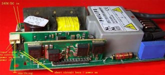
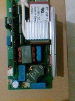
Hooked ballast back up to projector, can see it trying to ignite globe, can see component FSI on ballast img 1 from post3, actually lights up & gives 3 pulses.
Still unsure which pins to short as image from YWH looks different to my ballast
Did manage to find schematic for projector, too big to attach (2.9MB), anyone want to look at a copy email me & will forward it.
Hooked ballast back up to projector, can see it trying to ignite globe, can see component FSI on ballast img 1 from post3, actually lights up & gives 3 pulses.
Still unsure which pins to short as image from YWH looks different to my ballast
Attachments
Attachments
Tried shorting pins from ballast to CPU didn't work.
Did manage to find schematic for projector, too big to attach (2.9MB), anyone want to look at a copy email me & will forward it.
Hooked ballast back up to projector, can see it trying to ignite globe, can see component FSI on ballast img 1 from post3, actually lights up & gives 3 pulses.
Still unsure which pins to short as image from YWH looks different to my ballast
hi I am looking for him/it electric scheme infocus lp730 and of his/her ballast
if her a copy kindly sends me in pdf I would be her thankful
I attach link with my gallery of photo to make the ballast see her
thanks
Email: cazzola@tiscali.it
IMG_0059 | Flickr - Photo Sharing! /
control%20wires | Flickr - Photo Sharing! /
- Status
- Not open for further replies.
- Home
- General Interest
- Everything Else
- The Moving Image
- DIY Projectors
- Trick PalmPro 7756PA lamp circuit