Evening all,
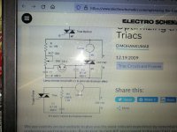
Please help me understand this scenario. I have build this circuit to drive a smallish transformer. 220Vac input on primary and 22VAC output on secondary. The primary resistance is about 34 ohm. This is the circuit that I have used. I'm using a BTA16-600BW triac and the circuit works OK. But what confuses me is when I test the output of the transformer using the triac control then I can adjust the voltage from about 8VAC to 22Vac which is good, but when I connect the secondary output to a rectifier bridge rectifier with a 0.1uf polyestercap just for testing then the confusion starts. The DC stays around 35VDC and cannot be adjusted much. I'm using a true rms Fluke to test. This confuses me completely. I have even removed the snubber circuit over the triac as it is not needed with these new triacs. I have connected the hot or live conductor to MT1 as this is what the datasheet say's which is different from this circuit.
plse help this flabbergasted man understand.
Attachments
I don't have a complete answer, but the DC voltage across the capacitor will depend on the peak voltage rather than the RMS voltage. That must have something to do with it.
The transformer will buzz, and may also overheat, as soon as you try to draw some power from it. Standard mains transformers don't like a chopped sine wave at the input. Don't use a valuable transformer for this experimentation. The triac itself may require a heatsink. If it breaks, replace it with a BTA16-800BW. The regulation is not linear because, as MarcelvdG said, you are filtering a distorted sinewave with a superimposed pulse. The DC voltage at the output will behave better when you add a load because the pulse will be flattened, but there will be switching noise and regulation will be poor.
You didn't say if you had a load connected? Otherwise you'll just be measuring the peak voltage on a capacitor that's never discharged.

The rectifier will cause the capacitor on the output to charge to the peak voltage. So if you capture a quarter cycle with the TRIAC you'll see the full 22*sqrt(2) = 31 V on the output. Seeing 35 V without load is not out of the ordinary. If you start at the full voltage and turn down the dimmer the capacitor will charge to the full 31-35 V and stay there. If you start from the low end you'll probably find the the voltage is lower.
You need some load to discharge the capacitor between charging pulses. Try adding a 1 kΩ across the capacitor on the output of the rectifier.
What's your goal here?
Tom
You need some load to discharge the capacitor between charging pulses. Try adding a 1 kΩ across the capacitor on the output of the rectifier.
What's your goal here?
Tom
Thanks guy's, yes I did not have a load on the output, I will try that . I have a BTA40-800 triac as well should the BTA16-600 fail. This will be an adjustable supply used to do etching in saltwater on knife's blades. The circuit the guy were using in the original youtube video did not use a controller at all. He just had a 24VA 24Vac transformer with a switch for choosing between AC and DC output for the etching. I just want to be able to adjust the voltage for faster or slower etching. I have used this circuit before when I build a controller for a 4Kw resistive kettle heater for brewing alcohol.
Morning all,
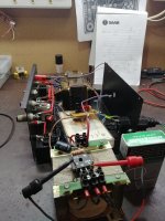
This is just to compare the sizes of transformers. The bigger original trannie has a primary resistance of 17R , the other freestanding one is about 34R, almost double. The original trannie which has a much bigger VA started buzzing at about 80% of the secondary output but with the freestanding trannie there is no buzzing at all. I have put a load resistor over the bridge and had to disconnect the capacitor to make it work. DC is now adjustable from 4 to 22VAC. I will the cap out, that should sort it, thanks for advice.
This is just to compare the sizes of transformers. The bigger original trannie has a primary resistance of 17R , the other freestanding one is about 34R, almost double. The original trannie which has a much bigger VA started buzzing at about 80% of the secondary output but with the freestanding trannie there is no buzzing at all. I have put a load resistor over the bridge and had to disconnect the capacitor to make it work. DC is now adjustable from 4 to 22VAC. I will the cap out, that should sort it, thanks for advice.
Attachments
A variac or auto transformer would be a better option. I grabbed the image below from eBay as an example.

Tom
Tom
Thanks Tom, yes you see the negative electrode is held in your hand, so that is why you need isolation from the mains. I suppose it is also good practice to earth one of the secondaries to the chassis in case of a fault.
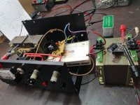
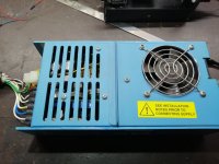
Guy's, I have tested the setup and it works good but the transformer is getting hot too quick. I'll have to install a fan. I think the thing is too over complicated on second thoughts. Some people use 6VDC at 4A and some use 24VAC at 1A. I might just as well use this Lambda smps. The 5VDC at 25A or 12VDC at 7A supply or 24VDC at 7A.
Attachments

- Home
- General Interest
- Everything Else
- Triac trouble