Attached is a LP section of either a 2.5 ways or a 3.5 ways speaker. To calculate for L3, I’m curious whether the speaker W1 could be considered as a capacitor, so the calculation can follow standard third-order formula.
Or are there any means to calculate L3 except using simulation softwares, i.e., VituixCAD, REW, etc.? (I can use them but just curious if there’s an alternative method, even hand calculation, available.)

Or are there any means to calculate L3 except using simulation softwares, i.e., VituixCAD, REW, etc.? (I can use them but just curious if there’s an alternative method, even hand calculation, available.)
We would need to know if W1 and W2 are identical or not. Or is W2 meant to be a subwoofer and not meant for higher frequencies.
That looks like a standard second order crossover. If the woofers are identical then I would guess L3 is for bass boost and would be somewhat larger in value compared to L2. In that case, W1 would handle most of the lower range. W2 would start when you hit rolloff of W1.
That looks like a standard second order crossover. If the woofers are identical then I would guess L3 is for bass boost and would be somewhat larger in value compared to L2. In that case, W1 would handle most of the lower range. W2 would start when you hit rolloff of W1.
Yes, they are identical.We would need to know if W1 and W2 are identical or not.
Your assumption is correct.If the woofers are identical then I would guess L3 is for bass boost and would be somewhat larger in value compared to L2. In that case, W1 would handle most of the lower range. W2 would start when you hit rolloff of W1.
The objective of this question is the desire to convert the existing 3-way speakers to 3.5-way system. I built 3-way 4-driver system containing a 0.75” tweeter, a 1.5” dome midrange, and dual 10” woofers per cabinet. The problem is the 1.5” mid cannot reproduce any lower frequency. So the dual 10” woofers have to be crossed over at higher point, approx. 800Hz. And I found that in order to boost bass, reducing mid and high outputs, the dual 10” were lifted all their operating range, not only bass region but mid-bass region. So there’s excessive mid-bass boosted. My expected solution is to convert them to 3.5-way system that could allow W1 and W2 reproduce bass and mid-bass independently. In short, W1 would be crossed at 800Hz the same, while W2 would be crossed at somewhere lower, such as 150Hz, etc.
Last edited:
I would simply give each woofer it's own crossover. Maybe simulate this idea in a Vituxcad or the like. At least measure it. You could have some funny results.
I know quite a few 2.5 way speaker, if you could save on parts with this cirquit, I'm pretty sure they would have used it. You are playing with 4 coils, 4 resistors and a cap if we see it simple. 2 of the coils change resistance over frequency. May not give a pretty output
I know quite a few 2.5 way speaker, if you could save on parts with this cirquit, I'm pretty sure they would have used it. You are playing with 4 coils, 4 resistors and a cap if we see it simple. 2 of the coils change resistance over frequency. May not give a pretty output
W1 can't be considered a capacitor at all, it's basically a resistor + inductance, with a bit of capacitance. I would definitely use a simulator. W1 in parallel with W2 and L3 in series is like one bass driver of increasing impedance. L3 serves, for example, to compensate for the baffle step. In order for L2+C2 to do their job as a second order filter, the impedance of W1+W2/L3 should first be corrected by an additional R-C to be approximately constant, say about 4 ohm if W1 and W2 are 8ohm. I will not go into the question of the actual frequency range of the drivers themselves, that is another part of the story. The only correct way is to measure the FR range and impedance, simulate, measure and correct (multiple times probably).
Last edited:
https://audiojudgement.com/impedance-equalization-circuit-zobel-network/
I use ARTA (LIMP) to measure impedance and TS parameters. I think it can also be done with REW, it's free software, but I don't use it. It is certainly easier and simpler for you to make separate crossovers for each woofer as suggested by @Turbowatch2 . You measure their individual impedances and perform correction with Zobel. If you go for your solution, then changing L3 also changes Zobel, that's more complicated.
Some drivers have no increase in impedance with frequency, or it is very small. These are the ones that have a copper or aluminum shorting ring on the magnetic pole piece. They do not require impedance compensation.
Last edited:
It's respectable that you're doing it that way, feel free to ignore this post as it is kind of cutting corners to use a simulator.
What I wanted to show was trends. Without the capacitor you have a couple of cascaded RL filters. In this screenshot they are the two blue dashed plots. One is an order steeper than the other as expected. (sometimes the second inductor is a larger value.)
Three other things can be seen on the red/green plots that correspond to the full (with capacitor) circuit. They are even steeper, they can potentially start out at a different slope and then kink as can be seen, and they are somewhat interdependent.
In order for textbook passive crossover filters to work you need to meet the conditions they were designed for, namely a zero output impedance source and a fixed impedance load. So a woofer at the low end has an impedance peak due to resonance and at the high frequency end it has a rising impedance due to the inductance. Adding a network across the woofer to flatten the impedance in the crossover frequency region is the start. Then you can treat the woofer with network as a fixed resistance for the crossover calculations. Of course it will be much quicker to use software like Xsim and then just look at the response while you adjust the coil value by moving the mouse scroll wheel and watch the response graph update as fast as you move the value up and down.
Yes, you are correct ... BUTfor textbook passive crossover filters to work
not all drivers offer themselves to a 'text book' scenario or theoretical simulation. Sometimes measurement & highly custom design are required 🙂
I'm correct. No buts about it. Xsim relies on measurements of the driver and simulates the coils, caps, resistors or active filters with all the fidelity required. Maybe you're not familiar with it.
It's respectable that you're doing it that way, feel free to ignore this post as it is kind of cutting corners to use a simulator.
What I wanted to show was trends. Without the capacitor you have a couple of cascaded RL filters. In this screenshot they are the two blue dashed plots. One is an order steeper than the other as expected. (sometimes the second inductor is a larger value.)
Three other things can be seen on the red/green plots that correspond to the full (with capacitor) circuit. They are even steeper, they can potentially start out at a different slope and then kink as can be seen, and they are somewhat interdependent.
View attachment 1391865
That is what I'm concerning as well.
The purpose of this mod is to convert the 3 ways speakers to 3.5 ways in order to let the two woofers, upper and lower units, be able to reproduce bass and mid-bass independently. The 3-way configuration whose midranges are so small such as 1.5-2" dome type was limitedly tuned when the midranges and tweeters were attenuated for emphasizing bass response, unfortunately, the mid-bass was also emphasized. This was resulted from the high crossover point of the woofers due to the disability to lower crossover point of the midranges anymore.
The ADS L1590/2 speakers are an example here. Below are crossover schematic and its electrical response. (I know it should be acoustical, however, the electrical response was used for educational purpose.)
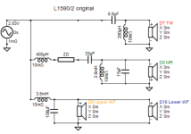
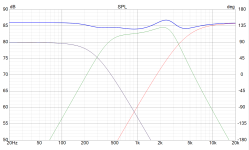
Using VituixCAD to simulate the result. It's possible to do so. But it was succeeded by randomly selecting all values.
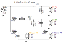
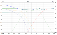
My goal is to find the alternative ways that doesn't required selecting values randomly. And an empirical formula is still better and acceptable for me.
Attached is a LP section of either a 2.5 ways or a 3.5 ways speaker. To calculate for L3, I’m curious whether the speaker W1 could be considered as a capacitor, so the calculation can follow standard third-order formula.
Or are there any means to calculate L3 except using simulation softwares, i.e., VituixCAD, REW, etc.? (I can use them but just curious if there’s an alternative method, even hand calculation, available.)
View attachment 1391442
If the corner frequency of the low-pass filter L3-W2 has to be much lower than that of L2, C3 and W1, then you could to a first approximation treat the branch L3-W2 as an open branch when calculating L2 and C3.
If not, then it gets complicated. I have tried to calculate the transfer without this assumption, treating W1 and W2 as resistors (you can always add impedance correction networks to make them sort of resistive), and set the coefficients of the transfer function to desired values, but ended up with an overdetermined system of equations when the resistances of W1 and W2 and the inductance of L3 are given. You only have two values (L2 and C3) to set three poles then.
Last edited:
If the corner frequency of the low-pass filter L3-W2 has to be much lower than that of L2, C3 and W1, then you could to a first approximation treat the branch L3-W2 as an open branch when calculating L2 and C3.
Wonderful! I've tried your suggestion of treating L3-W2 as an open branch and assuming corner frequency for W2 at about 100Hz or below.
So, there remains only W1 left in the circuit. L2 and C3 would see only impedance of W1 which is twice the original 3-way system says a single 8-Ohm woofer instead of 4-Ohm--two paralleled 8-Ohm woofers.
Therefore, I started changing L2 and C3 by double L2 values and halve C3:
L2 = 3.5mH --> 7mH
C3 = 100uF --> 50uF
And the L3 is doubled L2 to make sure there's low frequency enough that the assumption would still be valid; L3 = 14mH, it's quite high but still practical IMHO.
Here is the result.
Original 3-way system:
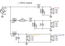
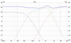
Modified to 3.5-way system:
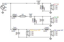
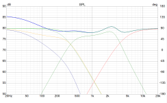
I'd love to hear any inputs.
You've given the second system an extra -6dB. Doesn't the original crossover manage baffle step?
No, they don’t have that in my opinion. As I can see, there are only 2 components for the LP of woofers, a 3.5 mH coil and a 100uF cap.Doesn't the original crossover manage baffle step?
There are other ways to manage it. Choosing drivers of different sensitivity and controlling the crossover frequency to coincide with the step. Also using the existing components to do more than one duty.
My question was more a case of whether you'll end up with too much bass after this?
My question was more a case of whether you'll end up with too much bass after this?
- Home
- Loudspeakers
- Multi-Way
- Treating a speaker as a resistor, a capacitor, or an inductor
