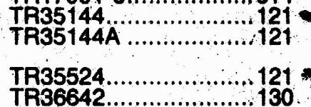
Hi all, I'm sitting here typing this with a headache the size of Cleaveland. Transistors are way harder to self teach than tubes. I'm working on a 1964 Fisher model 59 hybrid which I can't find a schematic or service manual for anywhere. To make a long story short, I'm looking for some transistors. It has 4 per channel and two of them are shorted thanks to a mucked up variable resistor (bias pot). I'm planning on keeping this forever due to sentimental reasons, so I figured I would just replace them all (recap and retube are complete). Word has it that these amps had a tendency to blow up channels, which this one had apparently done at one time or another. One side has had the transistors and interstage TX replaced. My problem is that I don't understand how to order the transistors or cross the numbers. A search here got me to the NTE site where the RCA# TR35144 crossed to an NTE121, and the RCA# 35524 crossed to a NTE181. I would have thought that I would have needed 180s and 181s. Can anyone help an old tube guy give this old Fisher a few more years of singing. Thanks, Jay
I'm working on a 1964 Fisher model 59 hybrid which I can't find a schematic or service manual for anywhere. To make a long story short, I'm looking for some transistors. It has 4 per channel and two of them are shorted thanks to a mucked up variable resistor (bias pot). I'm planning on keeping this forever due to sentimental reasons, so I figured I would just replace them all (recap and retube are complete). Word has it that these amps had a tendency to blow up channels, which this one had apparently done at one time or another. One side has had the transistors and interstage TX replaced. My problem is that I don't understand how to order the transistors or cross the numbers. A search here got me to the NTE site where the RCA# TR35144 crossed to an NTE121, and the RCA# 35524 crossed to a NTE181. I would have thought that I would have needed 180s and 181s. Can anyone help an old tube guy give this old Fisher a few more years of singing. Thanks, JayHi Jay,
They are probably Germanium transistors, and you do need a complimentary pair. It may be possible to rework it to use silicon transistors.
-Chris
They are probably Germanium transistors, and you do need a complimentary pair. It may be possible to rework it to use silicon transistors.
-Chris
Yes, I beleive you are correct. I remember something about geranium on one of the data sheets I looked at, at PE. Seems as though the part numbers reflected matched pair with a MP suffix, and Complimentary pair with MCP. Would I be correct in assuming that a complimentary pair would be one NPN and one PNP which have been matched? I apologize for the rookie nature of my questions, but I have really only dealt with tubes, capacitors, and resitors in the past. These transitors and associated "lingo" are pretty much Greek to me. They are apparently much less forgiving to the novice as well. At least tubes "red plate" for a few seconds before self destructing.😀 I really appreciate the help, Jay
At least tubes "red plate" for a few seconds before self destructing.😀 I really appreciate the help, JayHi Jay,
It would be nice if the complimentary pairs were matched. Don't expect that to be the case. It's not terribly harmful if they aren't.
What you need to do is figure out what the total supply voltage is. If you have positive and negative supplies, add them together. If it's a single supply with an output capacitor, the higest potential is the supply voltage. Your new part has to be rated for this voltage plus a safety margin. It's common to use 120 V devices when the total supply voltage is 80 VDC.
What is the model number of your set? There are good places to buy manuals and reproduction manuals.
-Chris
Yep, I measure 35v and -35v, so 120 would sound about right with 50v safety margin. From my research so far, it's looking as though these are Geranium and about 25 bux a pop for NTEs at mouser. It's a Fisher model 59A which uses 1 12AX7 and two 6HU8s in front of 8 transistors (2 pair per channel) for outputs. I've searched everywhere I can think of for a service manual and or schematic, with no luck. I'm thinking they didn't make these for very long. I wonder if some of the very early Fisher SS stuff would have a similar output topology? Any ideas on where to buy a service manual would surely be appreciated too. Thanks, Jay
It's a Fisher model 59A which uses 1 12AX7 and two 6HU8s in front of 8 transistors (2 pair per channel) for outputs. I've searched everywhere I can think of for a service manual and or schematic, with no luck. I'm thinking they didn't make these for very long. I wonder if some of the very early Fisher SS stuff would have a similar output topology? Any ideas on where to buy a service manual would surely be appreciated too. Thanks, JayAnatech, Just wanted to follow up with a thank you. I think I have the deal figured out now. I even found a nice looking lot of ECG 121s (NOS) on epay for 10 bux. This has, and will continue to be a good learning experience for me, thanks to folks like you, who are willing to help.😉 Thanks Again, Jay
BTW, I'll be sure to let you know how she turns out.
BTW, I'll be sure to let you know how she turns out.
Hi Jay,
Good job.
These are one of those times when ECG or NTE parts are about the only thing you can use without getting very lucky or wasting a great deal of time.
Make sure you measure the leakage on these before you install them. Germanium transistors are expected to be a little leaky. Silicon parts have extremely low leakage, none for our purposes here.
-Chris
Hi,
I'm working on fixing this same model, and likewise have not been able to find any information on it. In one channel, all four output transistors are blown, and I would like to find replacements.
In tracing the circuitry and testing the remaining good parts in the other channel, I find that all four transistors are PNP and appear to be germanium.
If I use the NTE cross reference, type 35524 gets cross referenced to NTE181, which is a silicon NPN power transistor, whch doesn't seem correct. Type 35144 cross references to NTE121, which is a germanium power transistor, so it may be correct.
Does anyone know what these transistors should be? Does anyone know of a source for a schematic or parts list for this unit? As mentioned above, I wonder if this was in production for only a very short time. I see virtually no information anywhere on this model R-590 (amp chassis 59A).
These should all work but perhaps not as optimal as the originals:
2N457B: S-L, 60V, Ueb=20V, 5A, 50W, 0,43MHz
---AL102..03
---AUY21..22
---2N1545..48
2SB375: S-L, 150V, 9A, 30W
--- AU107
--- AU110
--- AU113
--- AU213
--- 2N5324
2SB471: NF-L, 60V, 10A, 30W
--- AL100..101
--- 2N2289
--- 2N2292
--- 2N2527
2N457B: S-L, 60V, Ueb=20V, 5A, 50W, 0,43MHz
---AL102..03
---AUY21..22
---2N1545..48
2SB375: S-L, 150V, 9A, 30W
--- AU107
--- AU110
--- AU113
--- AU213
--- 2N5324
2SB471: NF-L, 60V, 10A, 30W
--- AL100..101
--- 2N2289
--- 2N2292
--- 2N2527
Thank you very much for the help. The incorrect cross reference is the online one at the NTE website: NTE online cross reference .
If you enter 35524 there, you get NTE181. That is probably what jaymanaa was using as well. I suspect it's giving incorrect information for this particular part number.
I should be able to track down either some NTE121s or one of the alternatives you've listed.
If you enter 35524 there, you get NTE181. That is probably what jaymanaa was using as well. I suspect it's giving incorrect information for this particular part number.
I should be able to track down either some NTE121s or one of the alternatives you've listed.
Do not trust that site. I've found errors on many occasions. My ECG book appears to be more accurate, not that I'm using it frequently.
/Hugo
/Hugo
RS stocks
AD149 3.5A 22.5W 50V
and
Germanium NPN/PNP transistor,AD161/AD162 3.0W
about $10 a pop
AD149 3.5A 22.5W 50V
and
Germanium NPN/PNP transistor,AD161/AD162 3.0W
about $10 a pop
Netlist said:These should all work but perhaps not as optimal as the originals:
...
2SB471: NF-L, 60V, 10A, 30W
...
I ordered some 2SB471s off e-Bay and installed them for a successful fix. As someone pointed out above, the biasing scheme in this amp can cause problems. There are four low-resistance potentiometers that were originally used to tweak the bias at the factory. Unfortunately, today they don't make very good contact and generate a lot of noise and cause the bias to wander all over the place. Replacing each of the four pots with a 5.6 ohm rfixed esistor seems to be a very definitive fix. Much more stable, and no noise.
Thanks again for the help with finding suitable replacements for the transistors!
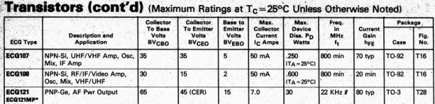
according to Net's posted datasheet, the nte121 is 45Vce0.
This is far too low for a supply of +-35Vdc.
What's involved in changing to silicon outputs?
This is far too low for a supply of +-35Vdc.
What's involved in changing to silicon outputs?
This is why, Andrew:
He just wants to stay with the original vintage design.
And this is what I would try do, too 😉
Lineup regars
jaymanaa said:I'm working on a 1964 Fisher model 59 hybrid which I can't find a schematic or service manual for anywhere.
To make a long story short, I'm looking for some transistors.
It has 4 per channel and two of them are shorted thanks to a mucked up variable resistor (bias pot).
I'm planning on keeping this forever due to sentimental reasons, so I figured I would just replace them all (recap and retube are complete).
---
Thanks, Jay
He just wants to stay with the original vintage design.
And this is what I would try do, too 😉
Lineup regars
Hi,
I realise that we want to keep the amp physically looking the same.
If it's just a case of replacing the germanium To3 with more robust and adequately rated silicon To3 then why not change? Save money and increase reliability
So I ask again
I realise that we want to keep the amp physically looking the same.
If it's just a case of replacing the germanium To3 with more robust and adequately rated silicon To3 then why not change? Save money and increase reliability
So I ask again
What's involved in changing to silicon outputs?
Hi Andrew,
If the output stage is an old "Lin" type topology the very low turn on volts (around 0.15 Vbe) of Germanium helps to keep crossover distortion at bay. Many old amps didn't use a vbe multiplier, you got a thermistor if you were lucky. You can swap for silicon but unless adequate thermal management is employed you could run into thermal problems, or have audible distortion.
My first amp used a pair of AD149's -- happy days.
- Status
- Not open for further replies.
- Home
- Amplifiers
- Solid State
- Transistor Selection