The BC639 or MPSA06 will do I would think, not quite as high gain on average but voltage is suitable.
The BC639 or MPSA06 will do I would think, not quite as high gain on average but voltage is suitable.
Those have a different pin out.
I have to agree the MPSA06 is different but the BC639 is the same pinout looking at the datasheets on line.
The MPSA06 would need its pins bending, a route I have travelled many a time fixing old kit with obsolete / unobtainable parts. 😉 I find the MPSA a useful general purpose (and cheap) device.
The MPSA06 would need its pins bending, a route I have travelled many a time fixing old kit with obsolete / unobtainable parts. 😉 I find the MPSA a useful general purpose (and cheap) device.
I thought the Japanese transistors were different from almost every one else. There are some exceptions I know, but I didn't check on that one.
The exact part is still available at the link I posted for $0.20 in singles.
The exact part is still available at the link I posted for $0.20 in singles.
Could someone tell me where i need to put my two leads with my dmm to test for idle current on my driver board? I have no schematics for this or anything Hard to find!, so i would just be testing what it is already and adjusting both for the same.Its for a Project/one 1500
thanks!
thanks!
Attachments
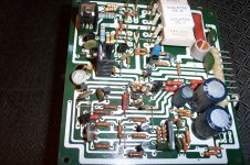
Measure across the .47ohm 5watt resistors. BTW- I noticed they don't all match. .5ohm and .47ohm... It would be a good idea to have them all the same (even though I know they're close). If you have the opposite channel to measure as a reference, you can set it to match. It'll be millivolts, maybe 10-20mV or so... Just a guess. Set it, and see how warm it gets just sitting idle, with no signal.
also the pot in the middle of the board is the bias one..
That pot may be burned. Check the feel ween turning it gently. It should feel very smooth. Also check it with an ohm meter to confirm the value is correct and there are no open spots as it is adjusted.
It looks like you have a bad transistor and a burned resistor near the center of the board, so you may have a lot more problems.
BTW- I noticed they don't all match. .5ohm and .47ohm...
It looks like the one you can't see the value on might also be .5 ohm. If there are two .47 and two .5, it might be meant to be that way. If only that one is .5, then I agree that they should all be the same value. You should check these resistors to see if any have opened.
Yea Kinda a long story,lol I brought this out of storage from about not using it for 10 years, plugged it in and let it set for maybe a hour tops turned it on and at light volume it wnet into protect!.. so I then took it in to tech and he said the channel was blown. so i said fix it then afterwards see what it puts out for power.. He fixed and called me and said it was playing fine. I said did u check the output and he said no i forgot. So He hung up and said he would check it.. calls me back said he smoked the same channel!.. This time he blew out a couple of those transistors with the heatsink around them and those .47 watt resistors, so he replaced them with the .5 ones.. I didnt really like that!.. so anyway get it back and bring it home.. and am jamming to some zz top when it shuts off after about a hour!.. This time i decide to pull it apart myself and I see that blown transistor and the shoddy work he did with those resistors stacked up.. he said he didnt have the right ones so he did that to get the correct ohms. That is when i called him and he said he would fix it or refund my money and i said i would like my money back! which he did.. so now I am here fixing it myself, but want to know where to check for idle currents on other channel cause i think he set it wrong or something else maybe those resistors being off blew the channel? so do i check across all 4 of those white ones or just anyone of them? I am assuming u mean red on one said black on the other just to clarify?
thanks guys!
x
thanks guys!
x
Oh by the way this is rated at 150 WPC into 8 and was tested 300 into 4 ohms! Ok Let it set for maybe 20 minutes and am getting about 24 mv across all of them. I checked all 4 just incase... So what is that in Ma then?
Thanks Steve!Doesn't that sound High? When the tech tried to fix it he set it at 30 Ma maybe it was too low? but that wouldn't blow the channel would it? Also where do i get those white resistors then exactly as I have original?I have two of these units one that is working , I should check that one also? That one runs out strong!
No, that doesn't sound high to me. That is not the reason the channel failed. Check the working channel for bias also. Set the one you are working on to the same value.
You can get those resistors from most electronics supply houses. Here is one link.
280-CR5-0.47-RC Xicon Wirewound Resistors
You can get those resistors from most electronics supply houses. Here is one link.
280-CR5-0.47-RC Xicon Wirewound Resistors
Thanks Steve!.. So What is this I have been reading about taking measurments across the emitter resistors for idle current? or is that what I am doing?
That is what you are doing.
Ok I wish people that post about this stuff would say the white emitter resistors then ,lol... Thanks
- Status
- Not open for further replies.
- Home
- Design & Build
- Parts
- Transistor replacement