What method/s (circuit/s?) do you use to match differential transistors? 😕
How about complimentary transistors?😕
I mean other than a handy RS meter with hfe option or a curve tracer which is not usually found at your local RS store? 😉
Ideally transistors should be matched over the expected operating currents, not at one point only. So, how are you matchers doing it?
Any advice (and circuits) will be appreciated.😀
How about complimentary transistors?😕
I mean other than a handy RS meter with hfe option or a curve tracer which is not usually found at your local RS store? 😉
Ideally transistors should be matched over the expected operating currents, not at one point only. So, how are you matchers doing it?

Any advice (and circuits) will be appreciated.😀
I did not really match my Mj15003 with my JLH for ESL. I have 4 MJ15003 per channel, ideally they should all have equal share of the bias current. When making the chassis I kept in mind that I have easy access to measure and replace them. Apparently the best way to check them is in circuit. I have them running for an hour to let them stablized and check them. I keep swoping them until each of them have the same current each, in my case 2A each. But if you have too many transistors to match then my method is not good for you.
Regards,
Chris
Regards,
Chris
aborza said:Any advice (and circuits) will be appreciated.😀
The best thing is to use matched pairs. Check here.
These BC847BS are really cheap.
If you want to match single transistors do like this:
Make a diff stage (or the one you are going to use) with same currents and the voltage across the transistors. If the bases are connected with some resistance try to do the same in your test setup in order to get working conditions as much like the real stage as possible.
Connect a voltmeter across the collectors so you can measure the unbalance.
Keep the bases grounded (if you use +- voltage) or at the same potential (if you use signle supply voltage).
Let one of the transistors be there and change only one of them. Write down the offset for each transistor and place the transistor where you have written the numbers.
Then when you have a couple of transistors which creates the same offset, they will probely work good togheter.
Thanks all,
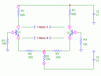
Peranders really got me thinking. So I came up with the following circuit.
It is not "exactly" like the circuit the transistors will be used in because Q2 in the operating circuit will not have a collector resistor and the match would be impossible. So I placed a 680R in the collector of Q2. It gives a place to take a measurement from and also balances the system. The simulator gives it a go!
R1,2,3,4,6 & 7 should be at least 1% types.
Notice the two meters.
Both meters will see 0V with a perfect match (unlikely of course). But Meter A between nodes 1 and 4 will be comparing points at about 31V and Meter B between nodes 3 and 6 will be comparing points at about .7V. Any comments as to which will result in better accuracy re the match?
Also the 16k can be varied to see if the transistors go off in different directions with different currents.
I do not know how close a match this circuit will show, but it should be better than nothing. 😀
Peranders really got me thinking. So I came up with the following circuit.

It is not "exactly" like the circuit the transistors will be used in because Q2 in the operating circuit will not have a collector resistor and the match would be impossible. So I placed a 680R in the collector of Q2. It gives a place to take a measurement from and also balances the system. The simulator gives it a go!
R1,2,3,4,6 & 7 should be at least 1% types.

Notice the two meters.
Both meters will see 0V with a perfect match (unlikely of course). But Meter A between nodes 1 and 4 will be comparing points at about 31V and Meter B between nodes 3 and 6 will be comparing points at about .7V. Any comments as to which will result in better accuracy re the match?
Also the 16k can be varied to see if the transistors go off in different directions with different currents.
I do not know how close a match this circuit will show, but it should be better than nothing. 😀
Attachments
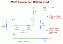
In regards to complimentary matching, I rustled around and found this circuit presented by Richard N. Marsh in AA during the 80's.
I think all the resistors in this circuit should be 1% or better for proper matching.
I hope you find it useful.
I think all the resistors in this circuit should be 1% or better for proper matching.
I hope you find it useful.
Attachments
aborza said:Thanks all,
Peranders really got me thinking. So I came up with the following circuit.
This was what I ment but I think it's sufficient with only measuring the collector voltage. This is a good approximation because you can't match every parameter.
May I ask what is the purpose of this matching? Don't forget what feedback will do.
I you have the opportunity test the BC847BS, good!
perancers,
Thanks for the reply,
I was not suggesting multiple tests. I was asking which point of measurement (A or B NOT A and B) would result in a more discriminating and accurate matching process.
As for the matched transistors (BC847BS), no luck. I was able to find dual BC847 surface-mount transistors for sale but not matched pairs.
As for the reason for matching:
1. It seems that, especially in the front end of an amplifier where error correction is focused, well matched devices will have less to deal with if they are not forced to correct for inherent distortion and offset that would otherwise be caused by poorly matched devices.
2. This is diy. The transistors are cheap and matching is like chicken soup to a cold. I couldn't hurt.
3. There is opinion that matching helps sonics and opposing opinion that feedback can cure all ills. By giving a diy'er the opportunity to try both, he can choose for himself.
4. Matching through-hole components gives the beginner options he would not otherwise have given poor soldering skills and the difficulties of handling surface-mount devices.
Ultimately I wish to post a site with some of these options for the beginner along with a versatile PCB to incorporate a variety of other options. It is a re-learning experience for me since I have been away from hands-on electronics for many years and I hope that in getting some of my questions answered, others will have questions answered as well.
The beginning of the quest can be found at: http://www.diyaudio.com/forums/showthread.php?s=&postid=90247#post90247
And I need all the help I can get.
BYW revised schematics are comming soon.
aborza said:A: I was not suggesting multiple tests. I was asking which point of measurement (A or B NOT A and B) would result in a more discriminating and accurate matching process.
B: As for the matched transistors (BC847BS), no luck. I was able to find dual BC847 surface-mount transistors for sale but not matched pairs.
As for the reason for matching:
1. It seems that, especially in the front end of an amplifier where error correction is focused, well matched devices will have less to deal with if they are not forced to correct for inherent distortion and offset that would otherwise be caused by poorly matched devices.
2. This is diy. The transistors are cheap and matching is like chicken soup to a cold. I couldn't hurt.
3. There is opinion that matching helps sonics and opposing opinion that feedback can cure all ills. By giving a diy'er the opportunity to try both, he can choose for himself.
4. Matching through-hole components gives the beginner options he would not otherwise have given poor soldering skills and the difficulties of handling surface-mount devices.
A: You are always interested in the collector currents, you shuold measure therefore the currents (or voltages over the collector resitors)
B: These BC8x7BS is monolithic pairs and have descent matching and is very cheap, only 20 cents!... but not suitable for newbeginners unless they are very handy. 0.025" between the pins isn't for everyone.
1-3: The whole idea of a differantial input stage is that the input transistors are excactly alike. If they are, the offset will be small, offset drift with temp will be small, the power supply rejection will be better and also the distortion will be lower.
The feedback can't cure or cancel defects in the first stage. Therefore it's important to make this stage as good as possible. Low noise is also often important.
Correction
Sorry,
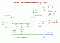
The prior schematic for the complimentary match circuit was wrong.
Here is the corrected schematic. But I am not sure this circuit will work properly either.
Note that the meter is suggested to read uA and is not in series. It would seem the measure should be in V's not A's. Also I put the circuit into simulation and it did not seem to work out sensibly.
Can someone check this out?
Attachments
At what potential shall the emitters be? I think something is wrong, either the 100 ohms resistor or the whole circuit.
Is your purpose to get a NPN/PNP pair? Can't you show the circuit they will be in?
Is your purpose to get a NPN/PNP pair? Can't you show the circuit they will be in?
Hi Aborza,
Re: differential transistors...
If I were a manufacturer I would probably buy lots of discrete transistors and have a production line tester to match up pairs. This would be the cheapest option for mass production.
Since the home designer isn't mass producing I see no reason not to get the supplier to do the work for you. Why not lash out on a specialist match pair part, like the SSM2210 from AD? These are expensive - several $s - but you get high gain, excellent matching, high FT and an easy life. Use parts designed for the job.
BAM
DIY guys are kinda cheap, in case you haven't noticed,
and would rather match them than give the manufacturer
any additional shekels.
and would rather match them than give the manufacturer
any additional shekels.
As an electronics newbie I have a question relating to this topic:
Do DMM transistor testers, which I believe show the gain of the device, have any use in matching transitors? Is this too obvious and am I missing something?
Do DMM transistor testers, which I believe show the gain of the device, have any use in matching transitors? Is this too obvious and am I missing something?
BAM
Went to the AD site and could not D/L spec sheets on the SSM2210.
But if it is an SMD they are quite troublesome to use. Through hole stuff is easier, especially for a beginner with poor soldering skills.
Did you check the comp match circuit to see if will work?
Went to the AD site and could not D/L spec sheets on the SSM2210.
But if it is an SMD they are quite troublesome to use. Through hole stuff is easier, especially for a beginner with poor soldering skills.
Did you check the comp match circuit to see if will work?
Nelson,
You are a tough act. I can never tell if you are serious!
But you surely know that it is often cheaper for a diy'er to buy a matched pair than to buy a bunch of devices and match a couple only to pitch the rest.
I will leave you all to figure out why a given diy'er matches devices.
You are a tough act. I can never tell if you are serious!
But you surely know that it is often cheaper for a diy'er to buy a matched pair than to buy a bunch of devices and match a couple only to pitch the rest.
I will leave you all to figure out why a given diy'er matches devices.
Mind you, at $20k+ a shot you'd think Nelson would put down his Fluke and settle for a $2 match pair for his input stage. Oh, but of course it has to be MOSFETs or the "spell" will be broken. 

Aborza,
This is a through-hole DIL package. Perhaps AD no longer make them under this part number. If you plug SSM2210 in your Yahoo search engine you'll quickly find a datasheet and probably a supplier. In any case there will be many similar matched bipolar IC about. Also try the Texas Instruments site and look for Burr Brown.
I have SSM2210 and SSM2220 for sale...... SSM22xx are obsolete, exact replacements are MAT02 and MAT03 from AD.
I have also the datasheets but the only thing that differs is the package, DIL08 vs. metal can
I have also the datasheets but the only thing that differs is the package, DIL08 vs. metal can
how I match
I match a bunch at a time, usually an entire tube or package of 50. With TO-220 and TO247 type devices, just write the parameters on the back with a sharpie and "bin" them -- I use metal containers, ergo no static problems. With the smaller transistors I use a small avery label. You can also use a pair of Avery Labels, say the 1 by 4 inch variety, and stick matching sets together. <p>You will find that the need for matching goes down when you buy transistors by the tube -- they are generally all cut from the same die. If you buy only what you need from some places you wind up getting mixed fairchilds, onsemi, etc.
I match a bunch at a time, usually an entire tube or package of 50. With TO-220 and TO247 type devices, just write the parameters on the back with a sharpie and "bin" them -- I use metal containers, ergo no static problems. With the smaller transistors I use a small avery label. You can also use a pair of Avery Labels, say the 1 by 4 inch variety, and stick matching sets together. <p>You will find that the need for matching goes down when you buy transistors by the tube -- they are generally all cut from the same die. If you buy only what you need from some places you wind up getting mixed fairchilds, onsemi, etc.
- Status
- Not open for further replies.
- Home
- Amplifiers
- Solid State
- Transistor matching methods.


