Is there any Transistor curve tracer that can measure hfe - Ic curve ? HP, TEK, DIY ?
I am not so much interested in the usual Ic - Vce set of curves.
I am not so much interested in the usual Ic - Vce set of curves.
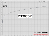
It's 0745 here in the Pacific timezone. I just took my mug of morning coffee into the workshop and measured hFE versus Ic for a ZTX857 NPN transistor that was lying on the bench. Equipment is a LockyZ curve tracer plus the comes-with-Windows "Snipping Tool" to get a screen capture. I told the tracer to sweep Ic from zero to 30mA while holding Vce constant at 10 volts. So at the far right end of the plot, the instantaneous power dissipation during measurement is 300 milliwatts.
_
_
Attachments
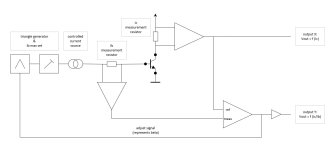
Thanks, for the Y we need divide Ic/Ib ?From scratch, that would be something like this.
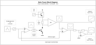
The adjust signal represents the beta and linearises the the Ic output.
Not tested or simulated!
Great, but this is not available anymore ?Equipment is a LockyZ curve tracer
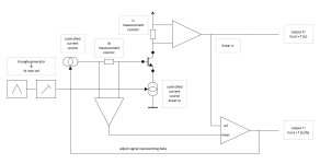
Insert a fixed cascode with voltage steps for variable Vce on the collector ?Not sure Ic is represented linear, an improved suggestion.
A few members of diyAudio are collaborators on various projects to design an improved curve tracer / curve tracing software. Have a look at these links:
(number 1)
(number 2)
(number 3)
(number 4)
(number 1)
(number 2)
(number 3)
(number 4)
hFE = Beta = Ic/Ib.Thanks, for the Y we need divide Ic/Ib ?
Better avoid those compex four quadrant miltipliers/deviders..
Not sure if that will fix Vce at a certain value. That would be a second user setting.Insert a fixed cascode with voltage steps for variable Vce on the collector ?
I'm going to dive in Mark's links...
While browsing through number 1, I realised that output Y is inverted in #3 (a 'valley' instead of a 'hilly' curve), so an inverting opamp should be added there.
number 1 is about transfer and output characteristics, but not seen a beta-tracer.
Also several digital circuits (the elaborous path, but promising - I leave that for the digital folks), and cops intervening...
I never have wrapped my mind around a beta-tracer, but the idea of Bernhard is very challenging!
This correction signal is that specific beta curve (inverted), but these extra conditions (constant Vce, NPN/PNP) makes it difficult.
number 2...
edit: and number 3
edit: number 4
nope...
Do it the easy way like LockyZ.
Build a "headless" curve tracer, i.e., an instrument without a graphical display. Instead, insist that the tracer hardware must connect (USB) to a computing device with a nice big high resolution display. Then run the curve tracer's control software AND the curve tracer's channel-DAC management software, on that computing device. Where you have infinite amounts of RAM and 64 bit floating point hardware.
To measure hFE versus Ic on the headless tracer
Set the collector voltage (DAC) to the user-provided Vce value. Set the emitter voltage (DAC) to zero.
Step Ibase from 0 to BigValue in steps of epsilon microamps per step. User provides BigValue and epsilon.
For each Ibase, measure Icollector. Then compute hFE_at_Ic = (Icollector / Ibase) using 64 bit floating point division.
When finished, plot hFE_at_Ic versus Icollector.
Victory.
Mark, you're right. The digital era is promising.
But I'm an analog man grad in 87. I sincerely leave that for the next generation.
I like puzzles to solve. There are many routes to find one's bliss.
But I'm an analog man grad in 87. I sincerely leave that for the next generation.
I like puzzles to solve. There are many routes to find one's bliss.

Is a four quadrant divider needed ?Better avoid those compex four quadrant miltipliers/deviders..
In your block diagram should`t the Vceset be below rmeas ? Because of the current dependent voltage drop across Rmeas. Or R is very small ?
INA is a BB instrumentation amp ?
There are some nice curves presented in Horowitz and Hill's textbook , example below. The logarithmic horizontal axis (Icollector) spans 4 1/2 decades of current, from 10uA to 50 mA
_
_
Attachments

A 3 1/2 digit panel meter could be used as digital hfe readout. 100mV for hfe 100
Or directly in the xy display. Any usable chips maybe in oscilloscopes ?
The voltage after the divider has to be sampled with S/H, even a cursor could be added.
Or directly in the xy display. Any usable chips maybe in oscilloscopes ?
The voltage after the divider has to be sampled with S/H, even a cursor could be added.
Last edited:
This tester makes spot measurements of beta for any arbitrary Vce, Ic:
https://www.diyaudio.com/community/threads/a-constant-ic-v-tester-v-master.349199/post-6072860
If the voltage driving the current-setting circuit is replaced with a sawtooth generator, it could be turned into a Hfe tracer
https://www.diyaudio.com/community/threads/a-constant-ic-v-tester-v-master.349199/post-6072860
If the voltage driving the current-setting circuit is replaced with a sawtooth generator, it could be turned into a Hfe tracer
If you want accute devide two electronic (volts, amps) values, in most cases yes. Unless the 'error signal tric' kicks in. And that happened!Is a four quadrant divider needed ?
In your block diagram should`t the Vceset be below rmeas ? Because of the current dependent voltage drop across Rmeas. Or R is very small ?
INA is a BB instrumentation amp ?
Rmeas is of a low value - should be scaled with current obviously (TO92 / TO126 / TO3 just as examples).
Any instrumentation amplifier: accurate and amplification adjustable.
Know anyone beside yourself who build this?This tester
It's impressive, but rather complex.
- Home
- Design & Build
- Equipment & Tools
- Transistor HFE - IC curve tracer?