basic information concerning the differences are described in detail here:
http://www.reallyreallyrandom.com/www/Zener_Theory_and_Design.pdf
and here:
https://www.onsemi.com/pub/collateral/hbd854-d.pdf
AI short form description as follow:
a TVS (Transient Voltage Suppressor) diode is used as an alternative to a Zener diode, particularly for dropping screen grid voltage in tube amplifiers. While Zener diodes clamp the voltage to a specific level, TVS diodes act more like a protector, absorbing over-voltage transients and shielding other components.
But I wonder, why such TVS diodes (TRANSZORB®) "SMAJ-5.0A" - for datasheet go to
https://www.vishay.com/docs/88390/smaj50a.pdf
very often causes a total failure of various components with 5V plug-in power supplies (because this TVS diode has an internal short circuit after a short time of use - i.e. works like a wire bridge between the plus rail and the minus rail).
In the moment I have 3 devices of this kind of electronic modules without any operating:
https://www.revitive.com
After looking for the most probably reason therefore I have found this video examples on youtube:
Revitive Circulation Booster | Won't turn on | Can I Fix It? (10:33)
Revitive Machine No Power Repair (5:35)
Faulty REVITIVE Circulation Booster | Can I FIX It? (3.15)
Always the shorting inside of the TRANSZORB® TVS diode "SMAJ-5.0A" was the reason - but the reason therefore again wasn't the 5V SMPS power supply.
I remember many previous repairs on other kind of assemblies that were operated with 5VDC, the total failure of which was also due to a short circuit of such TVS diodes. In these cases I always replaced it with a high power 5V1 Zener diode and additionally with a normal fast recovery diode BY299 to trim any transients in reverse polarity that may
occur - fortunately without any trouble with further use.
But what actually is the royal step to get on one hand optimal protection requirement and OTOH best reliability for the protection part itself (obviously TVS diodes like the SMAJ-5.0A isn't reliable)?
Thanks for an advice.
Use a "crowbar" on the 5v output.
A simple voltage spike detection circuit will trigger the thyristor, almost instantly, if the 5volt output rises above your preset voltage.
Just a 4v3 zener between the +ve output and the gate of the thyristor will cause the thyristor to conduct, like a "crowbar" and not release until the supply voltage is removed.
D1 4v3
R1 1k
R2 2k2
R3 10k
Q1 Tic126 or anything to suit
Very simple and 100% effective.
Attachments

I would shoot for 1500W pk devices like SMCJ5.0A. Yours is 400 W. Short mode is there by design - no overvoltage if device fails. The big ones can absorb few Joules.
Probably SMAJ-5.0A was chosen too tight but it should not stay in conductive state. Choose definitely one by another brand and test. Also check the maximum power the PSU can deliver and if necessary upgrade to SMCJ-5.0A as alexberg suggested. It may very well be a small spike can cause too high current in that device.
I recall having defective ones and then thought them becoming a short circuit is normal 😉
A Zener diode is by far NOT a suitable replacement.
I recall having defective ones and then thought them becoming a short circuit is normal 😉
A Zener diode is by far NOT a suitable replacement.
Last edited:
Very good information - thank you.
I'm now asking myself the fundamental question why such TVS diodes were never seen in older 5V assemblies, even when highly overvoltage-sensitive components such as TTL ICs and MCUs were already being used.
As far as I remember, this type of diode only came into use when more and more SMPS were used instead of 50/60 Hz transformers + classic 5V voltage regulators, and the capacitance of the ELCAPs between the voltage rails was significantly reduced at the same time.
Maybe switch-mode PS so as small capacitance between the voltage rails and TVS diodes for overvoltage protection is at whole much more cost-effective.
P.S.: the approach in post #2 with a TRIAC is for me the most interesting and convincing.
You seem to be very exact. In that light it would have been a good thing to make a list of what brand was defective most of the times. Also what power the PSU could deliver.
It could be that reliability of this wonderful 1 part solution depends on brand and/or (more likely) right application. It can be that its value and breakdown voltage are met too often at power on (my suspicion) combined with a (too) powerful PSU. Then using the next in line could be a solution so SMAJ-6.0A. Repetitive overvoltage so breakdown at every power on cycle is detrimental. Also lack of just enough series resistance and unexpected possible high short circuit current combined may play a role. Then the part was chosen wrong and a SMCJ-5.0A could be the definitive solution.
Please not “newer is worse” etc. I think these did not exist 20 years ago. Their reason for existence is to protect sensitive stuff from overvoltage a very fast and radical way what MOVs and Zener diodes could not do adequately enough.
Last edited:
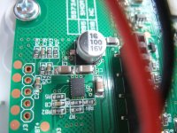
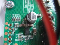
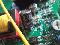
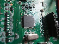
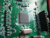
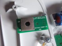
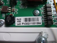
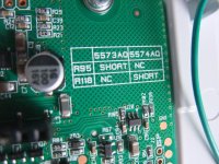
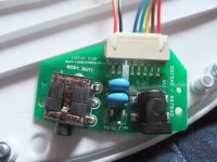
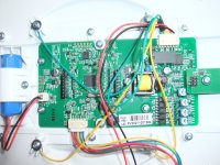
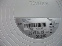
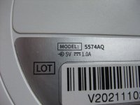
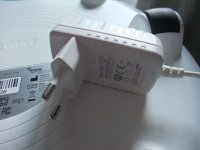
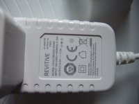
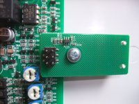
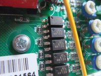
In the attachment some images of the wall wart power supply plug (5V/1A) and the PCB of the device (a little bit newer version than those from the videos in post #1). Amazing is, that a 5VDC power supply with nominal 1A can deliver more than 400W due a faulty overvoltage peak.Probably SMAJ-5.0A was chosen too tight but it should not stay in conductive state. Choose definitely one by another brand and test. Also check the maximum power the PSU can deliver and if necessary upgrade to SMCJ-5.0A as alexberg suggested. It may very well be a small spike can cause too high current in that device.
I recall having defective ones and then thought them becoming a short circuit is normal 😉
A Zener diode is by far NOT a suitable replacement.
Attachments
-
 Revitive Medic Package.JPG578.6 KB · Views: 14
 -
 Revitive Medic battery.JPG372.3 KB · Views: 15
 -
 Revitive Medic Charger-unit.JPG580 KB · Views: 15
 -
 Revitive Medic Charger-unit-II.JPG745 KB · Views: 13
 -
 Revitive Medic HF transf.JPG724.3 KB · Views: 12
 -
 Revitive Medic HF transf-II.JPG763.5 KB · Views: 12
 -
 Revitive Medic MCU.JPG533.5 KB · Views: 12
 -
 Revitive Medic MCU-II.JPG548.2 KB · Views: 12
 -
 Revitive Medic On-Off.JPG412.9 KB · Views: 12
 -
 Revitive Medic Package.JPG578.6 KB · Views: 11
 -
 Revitive Medic PCB Sticker.JPG464.6 KB · Views: 10
 -
 Revitive Medic PCB type.JPG610.3 KB · Views: 10
 -
 Revitive Medic PS-Jack.JPG547.9 KB · Views: 12
 -
 Revitive Medic whole PCB.JPG583.9 KB · Views: 12
 -
 Revitive Medic sticker.JPG401.5 KB · Views: 12
 -
 Revitive Medic sticker-II.JPG430.3 KB · Views: 10
 -
 Revitive Medic PS-I.JPG395.5 KB · Views: 10
 -
 Revitive Medic PS-II.JPG304.8 KB · Views: 10
 -
 Revitive Medic PCB-XIII.JPG539.6 KB · Views: 10
 -
 Revitive Medic PCB-XII.JPG728 KB · Views: 11
Tranzorbs are simply zeners with a high surge rating and specified for 8/20us surge ratings.
No regulated power supply should give any significant overshoot above the nominal 5V.
The SMAJ5.0 only starts to clamp somewhere between 6.40 and 7.00V, already high for many logic families.
No regulated power supply should give any significant overshoot above the nominal 5V.
The SMAJ5.0 only starts to clamp somewhere between 6.40 and 7.00V, already high for many logic families.
The way to find out is to measure the power on behavior with and without TVS (which are not Zener diodes).
Maybe it is not the power but the repetitive breakdown cycles at every power on. Manufacturer detected overshoot and solved that with a tightly chosen TVS, that kind of thing. Chicken-egg dilemma.
There must be a reason for failure.
Maybe it is not the power but the repetitive breakdown cycles at every power on. Manufacturer detected overshoot and solved that with a tightly chosen TVS, that kind of thing. Chicken-egg dilemma.
There must be a reason for failure.
Last edited:
I suspect the overvoltage protection is due to the SMPS having a long and somewhat unreliable feedback loop involving an opto-isolator.
Ed
Ed
- Home
- Design & Build
- Parts
- Transient Voltage Suppressor (TRANSZORB®, TVS) vs. Zener Diode - which Differences in Protection on 5V Modules