I want to add reverb to my clone Princeton, which already has tremelo, but chassis space is tight. The old Ampeg GU-12 used a hi impedance tank, and no xfmr, and one tube (for pre and post drive). Don't know what the impedance of that tank was, but current tanks I've seen have up to 1750R input, and 5000R out. Anyone know of any other xfmr-less designs? And is a small tank (less than 10in) worth using? Thanks!
Use the Op Amp, SS driven reverb, which 99% factories use today in their *tube* amps.
Yes, even Fender, Marshall, Orange, Laney, etc.
Old style tube + transformer driven reverb is nice, but nowadays only Boutique and a couple commercial models use it.
Check these schematics to see how they do it:
In the Hot Rod Deville they send the Preamp out, either from the last "clean" tube V2a or "dirty" from Master Volume R26 , selected with Relay K2a, to the SS Reverb circuit.
Part of the signal (Dry) goes straight to Power Amp input (TP23) through mixing resistor R40 , part of it goes to the Drive Op Amp U2a through C13 .
Not really complex, what complicates it *visually* is the complex switching involved using those pesky Fender jacks which are full of internal switches, but if nothing is plugged into them, the path is the one I describe.
You also have some signal attenuation, that's why you find here and there a few series resistors and others to ground, mainly because the raw tube signal may be way higher than what an Op Amp input can handle (30Vpp and preferrably a little less) , I can suggest proper attenuation if you post your preamp schematic.
U2a drives the high impedance tank, its output is reamplified through U2b , is controlled by Reverb pot R39 and then also goes to Dry/Wet mixing point TP23, through R38 .
So, although it may look complex, mainly because of the way it's drawn, it's actually quite simple and follows the classic recipe: part of the signal goes through a resistor, part is delayed, both are again mixed to get a reverb effect.
You need +/- 15V for them.
http://www.tangible-technology.com/schematics/fender/HR-Deville/Hot Rod DeVille.pdf
Marshall and others do a similar thing.
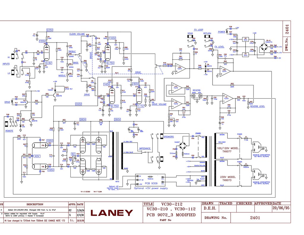
Here Laney also selects Clean/Dirty channels with a relay, and adds between preamp and power amp a nice Effects Loop and Reverb drive send/recovery circuit.
You may basically add this to your amp, and it's both more clear and useful than the Fender way.
As a bonus, it uses 2 Op Amps in parallel to drive the tank, to have more drive current available, but no big deal, you may use just one like most everybody else, so grand total is 2 x TL072 .... no big deal 😉
See that again both clean and dirty signals are attenuated, and the first Op Amp has gain less than 1 (0.5X)
These are just for reference, you can chop the basic circuit, which by the way is based on the generic one posted at the Accutronics site for anybody to use.
No need to reinvent the wheel 😉
Yes, even Fender, Marshall, Orange, Laney, etc.
Old style tube + transformer driven reverb is nice, but nowadays only Boutique and a couple commercial models use it.
Check these schematics to see how they do it:
In the Hot Rod Deville they send the Preamp out, either from the last "clean" tube V2a or "dirty" from Master Volume R26 , selected with Relay K2a, to the SS Reverb circuit.
Part of the signal (Dry) goes straight to Power Amp input (TP23) through mixing resistor R40 , part of it goes to the Drive Op Amp U2a through C13 .
Not really complex, what complicates it *visually* is the complex switching involved using those pesky Fender jacks which are full of internal switches, but if nothing is plugged into them, the path is the one I describe.
You also have some signal attenuation, that's why you find here and there a few series resistors and others to ground, mainly because the raw tube signal may be way higher than what an Op Amp input can handle (30Vpp and preferrably a little less) , I can suggest proper attenuation if you post your preamp schematic.
U2a drives the high impedance tank, its output is reamplified through U2b , is controlled by Reverb pot R39 and then also goes to Dry/Wet mixing point TP23, through R38 .
So, although it may look complex, mainly because of the way it's drawn, it's actually quite simple and follows the classic recipe: part of the signal goes through a resistor, part is delayed, both are again mixed to get a reverb effect.
You need +/- 15V for them.
http://www.tangible-technology.com/schematics/fender/HR-Deville/Hot Rod DeVille.pdf
Marshall and others do a similar thing.
Here Laney also selects Clean/Dirty channels with a relay, and adds between preamp and power amp a nice Effects Loop and Reverb drive send/recovery circuit.
You may basically add this to your amp, and it's both more clear and useful than the Fender way.
As a bonus, it uses 2 Op Amps in parallel to drive the tank, to have more drive current available, but no big deal, you may use just one like most everybody else, so grand total is 2 x TL072 .... no big deal 😉
See that again both clean and dirty signals are attenuated, and the first Op Amp has gain less than 1 (0.5X)
These are just for reference, you can chop the basic circuit, which by the way is based on the generic one posted at the Accutronics site for anybody to use.
No need to reinvent the wheel 😉
Last edited:
Excellent! Going SS solves many problems. Would you know what the reverb coil in and out impedances are? Thanks!
2 ways, try both and see whether they confirm or reject each other:
1) read the reverb tank letter code, the Accutronics site has a table covering all combinations.
Search and post it here for future reference.
2) measure DC resistance at the input and output coils, Accutronics again shows a table matching DC resistance to actual impedance at 1kHz.
In these simple SS solutions, you want high impedance (600 ohms or more) so they can be driven by a single Op Amp.
Marshall in some amps uses 200 ohms tanks, driven by 2 or 3 parallel Op Amps.
I like Rod Elliot's circuit:
Spring Reverb Unit For Guitar
I actually like the 2006 version more than the 2014 version:
https://web.archive.org/web/20130430042825/http://sound.westhost.com/project34.htm
Spring Reverb Unit For Guitar
I actually like the 2006 version more than the 2014 version:
https://web.archive.org/web/20130430042825/http://sound.westhost.com/project34.htm
Here's a link if you want to use a tube. Doug Circuits
As an alternative to the tube he suggests, you could use a 7247. It's half 12AU7 for send and 12AX7 for recovery.
Here's another article that goes well with the one Juan referred you to. It explains about as much as you need to know along with circuit examples.
https://www.amplifiedparts.com/tech_corner/spring_reverb_tanks_explained_and_compared
Last edited:
Use the Op Amp, SS driven reverb, which 99% factories use today in their *tube* amps.
........
You need +/- 15V for them.
..........
No need to reinvent the wheel 😉
I don't understand an easy way to generate the +/- 15 volt supply without an appropriate winding on the PT. So, for me that lack of knowledge (along with the need to use either a PCB or project board for the IC) is definitely a drawback.
Punch a hole and throw in another tube! (assuming your PT can heat it...)🙂
BTW, some non-boutique amps still have tube reverbs - the Carvin Vintage 16 is one example of an 'ordinary' amp with tube reverb (and no transformer).
Attachments
Last edited:
Now that we are defining your needs, I may suggest this project.
FWIW it was one of my first successful commercial projects, starting in 1969, I built and sold around 100 of them to my Musician friends.
It works very well, it's based on a circuit suggested by Hammond/Gibbs/Accutronics themselves (of course they wanted people to buy Reverb tanks 😉 ) and most important:
1) it's fed from a single supply (V+ only) instead of a symmetrical one as usually needed by Op Amps (+/- 15V)
2) they explain how to get the needed + 30V from the existing supply of your amp, whether SS (typically 40 to 60V) or tube , they show a graph up to +300V (and you might extend it to +400 or 500V)
3) they explain how to interface it to a Tube or SS amp.
Personally, in the case of a tube amp I'd add some clamping/protection diodes to avoid damaging it, they had *clean* tube amps in mind, both Hi Fi and Guitar (remember: 1968 project) .
Popular Electronics January 1968
just as a free sample:
you'll use the modern versions of those old transistors of course.
FWIW I remember myself making the PCBs painting the PCB tracks on bare copper with Mom's nail enamel , drilling them with a hand driven drill and "punching" aluminum panels with drills and files , doing all lettering with Dymo labelling tape and later with Letraset , fixed with transparent varnish.
Oh the joys of the early hobby, before it became a business 🙂
FWIW it was one of my first successful commercial projects, starting in 1969, I built and sold around 100 of them to my Musician friends.
It works very well, it's based on a circuit suggested by Hammond/Gibbs/Accutronics themselves (of course they wanted people to buy Reverb tanks 😉 ) and most important:
1) it's fed from a single supply (V+ only) instead of a symmetrical one as usually needed by Op Amps (+/- 15V)
2) they explain how to get the needed + 30V from the existing supply of your amp, whether SS (typically 40 to 60V) or tube , they show a graph up to +300V (and you might extend it to +400 or 500V)
3) they explain how to interface it to a Tube or SS amp.
Personally, in the case of a tube amp I'd add some clamping/protection diodes to avoid damaging it, they had *clean* tube amps in mind, both Hi Fi and Guitar (remember: 1968 project) .
Popular Electronics January 1968
just as a free sample:
An externally hosted image should be here but it was not working when we last tested it.
you'll use the modern versions of those old transistors of course.
FWIW I remember myself making the PCBs painting the PCB tracks on bare copper with Mom's nail enamel , drilling them with a hand driven drill and "punching" aluminum panels with drills and files , doing all lettering with Dymo labelling tape and later with Letraset , fixed with transparent varnish.
Oh the joys of the early hobby, before it became a business 🙂
Last edited:
Anyone tried the Accutronics/Belton Digital Reverb or DSP Modules (the BTDR and BTSE Modules)?
::::::::: Accu Bell Sound Inc :::::::::
If so is the Reverb similar to spring reverb in sound or quite different?
Hesitate to recommend these without someones experienced opinion but if the DSP Module provideds acceptable Reverb then the fact that you get Wah, Tremlo, Flanger and Chorus for "free" would make it attractive.
Cheers,
Ian
Hi Ian,
your url also contains recommandations by the manufacturer itselves, regarding spring reverbs. For the drive circuitry, I'd perfer the constant current layout.
Best regards!
your url also contains recommandations by the manufacturer itselves, regarding spring reverbs. For the drive circuitry, I'd perfer the constant current layout.
Best regards!
Now that we are defining your needs, I may suggest this project.
FWIW it was one of my first successful commercial projects, starting in 1969, I built and sold around 100 of them to my Musician friends.
It works very well, it's based on a circuit suggested by Hammond/Gibbs/Accutronics themselves (of course they wanted people to buy Reverb tanks 😉 ) and most important:
1) it's fed from a single supply (V+ only) instead of a symmetrical one as usually needed by Op Amps (+/- 15V)
2) they explain how to get the needed + 30V from the existing supply of your amp, whether SS (typically 40 to 60V) or tube , they show a graph up to +300V (and you might extend it to +400 or 500V)
3) they explain how to interface it to a Tube or SS amp.
Personally, in the case of a tube amp I'd add some clamping/protection diodes to avoid damaging it, they had *clean* tube amps in mind, both Hi Fi and Guitar (remember: 1968 project) .
Popular Electronics January 1968
just as a free sample:

you'll use the modern versions of those old transistors of course.
FWIW I remember myself making the PCBs painting the PCB tracks on bare copper with Mom's nail enamel , drilling them with a hand driven drill and "punching" aluminum panels with drills and files , doing all lettering with Dymo labelling tape and later with Letraset , fixed with transparent varnish.
Oh the joys of the early hobby, before it became a business 🙂
Shame I never saw this way back when. Looks like it would go well with the L'il Tiger amp. We blew the output transistors on that one enough times to lift off the traces. Actually good sounding amp for SS.
K.P.
Yes that is the best of the examples under the schematics tab on that website.
I think we can do better today, at the expense of a little added complexity. There are a lot of high output current opamps available these days and a pair of them could easily be configured to drive the tank input in a bridge arrangement.
For an example: This is perhaps one of the oldest dual "power opamp"s and probably not what I would use, but look at application pages on the datasheet to see how they drive a DC Motor in a bridge arrangement. I'd try that arrangement but perhaps with a more modern device.
Datasheet Link
http://www.st.com/st-web-ui/static/active/en/resource/technical/document/datasheet/CD00000054.pdf
The schematic you linked is MUCH simpler however.
Cheers,
Ian
Moreover, at least I'd not be able to tell you how to configure a bridge arrangement to work as a constant current source.
Best regards!
Best regards!
K.P.
Yes that is the best of the examples under the schematics tab on that website.
I think we can do better today, at the expense of a little added complexity. There are a lot of high output current opamps available these days and a pair of them could easily be configured to drive the tank input in a bridge arrangement.
For an example: This is perhaps one of the oldest dual "power opamp"s and probably not what I would use, but look at application pages on the datasheet to see how they drive a DC Motor in a bridge arrangement. I'd try that arrangement but perhaps with a more modern device.
Datasheet Link
http://www.st.com/st-web-ui/static/active/en/resource/technical/document/datasheet/CD00000054.pdf
The schematic you linked is MUCH simpler however.
Cheers,
Ian
Almost every 20W car amp bridges a pair of chips to get the power from 13.8V.
- Status
- Not open for further replies.
- Home
- Live Sound
- Instruments and Amps
- Transformerless reverb tank for tube amps