Hi!
I want som advice concerning how to best wire the mains transformer in my coming tubeamp. I need about 260 V@250 mA to the outbut tube and same voltage or maybe a little higer (se D) to the drivestage @20 mA.
In whitch case do I put the less stress to the transformer.
Regards Anders Brandt
I want som advice concerning how to best wire the mains transformer in my coming tubeamp. I need about 260 V@250 mA to the outbut tube and same voltage or maybe a little higer (se D) to the drivestage @20 mA.
In whitch case do I put the less stress to the transformer.
Regards Anders Brandt
Attachments
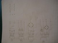
A will give you 0.707 X voltage with 1.414 X current.
B will give you 0.707 X current but 1.414 X voltage on each winding.
C will give you similar results to B per winding.
D must be a different transformer and a multiple of already described.
Don't forget, if the transformer is rated at 100V/A then that is all you can get, in any configuration.
None give either more or less stress on the transformer, the stress is down to smoothing capacitors and output drawn.
That explains it better than I can.Here is nice cheat sheet on the subject made by Hammond's company.
A will give 30% less current than B or C for the same regulation or temperature rise. D will give two different voltages, higher one will be limited to 0.1A RMS by the smaller winding.
Thank you for fast replies. I recon that D will be the best one to choose. The trans have a third winding like in the picture. And then it's more easy smooth the voltage to the first ampstage.
Yes, 'D' will give independent supplies, with one being a bit higher voltage than the other.
However, my preference is 'C'. The reason is that the total load (current) is placed fairly across the two similar 195 VAC windings. Since P = I²R, looking at just one winding (for analysis purposes), the I is halved. Its 'R' doesn't change. Therefore the P/P = (½)² or ¼. But of course, there are 2 windings involved, so ¼ ⊕ ¼ = ½.
Still, half the power dissipation during capacitor charge cycles … is a worthy outcome.
Moreover, the 'total power' available is at the limit of the transformer without balance issues to speak of. Supposing that the pair of 195 V windings are indeed well matched to each other. co-wound equal-turn windings are the best.
Down-wind of the full-wave bridge, is filtering … and tho' it wasn't part of the discussion, 'regulation'. I highly recommend active regulation (either absolute value, or fraction-of-quiescent) via MOSFET series regulators (plural) to obtain the output, and driver voltages you desire. The technique is simple, the results better than expensive high-current chokes or large-can capacitors. It is 2020, after all!
Anyway, I apologize for the unsolicited off-topic opinion. It seemed related.
⋅-=≡ GoatGuy ✓ ≡=-⋅
- Home
- Amplifiers
- Tubes / Valves
- Transformer Wiring