I'll try to make this clear as possible.
I bought some PE toroids that are 14VCT (when in phase!). They produce +/-10.5VDC after rectification and caps. I need to get them up to a +/- 12VDC or +/- 15VDC rectified supply.
I understand that the transformers can be wired in series... What are the precautions necessary? Are all the CT's tied together to form ground down stream? So the scheme would be... (ASCI on!)
..................|......|..............|.....|
...................120VAC 120VAC
..................______ ........._______
..28VAC ~ tranny ~ tie ~ tranny ~ 28VAC
.....|..............|................|..............|
.......................CT----tie-----CT
.................................|
...............................___
...............................___
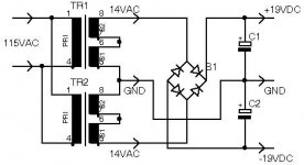
It's also possible to combine the rectified outputs of two transformers, right?
............ ______ ~.........+ Vcc+
tranny |..................rect
............ ______ ~......... -
...................................|. . . . . .<--is this right????
...Both CT's--------------|-----------ground -0-V
..............______ ~ ........+
tranny |...................rect
..............______ ~ .........- Vcc-
Which is preferable?
Help a nuub out.
Thank you in advance!
EDIT: Sorry for the periods. It seems that leading spaces don't work in the message window.
I bought some PE toroids that are 14VCT (when in phase!). They produce +/-10.5VDC after rectification and caps. I need to get them up to a +/- 12VDC or +/- 15VDC rectified supply.
I understand that the transformers can be wired in series... What are the precautions necessary? Are all the CT's tied together to form ground down stream? So the scheme would be... (ASCI on!)
..................|......|..............|.....|
...................120VAC 120VAC
..................______ ........._______
..28VAC ~ tranny ~ tie ~ tranny ~ 28VAC
.....|..............|................|..............|
.......................CT----tie-----CT
.................................|
...............................___
...............................___
It's also possible to combine the rectified outputs of two transformers, right?
............ ______ ~.........+ Vcc+
tranny |..................rect
............ ______ ~......... -
...................................|. . . . . .<--is this right????
...Both CT's--------------|-----------ground -0-V
..............______ ~ ........+
tranny |...................rect
..............______ ~ .........- Vcc-
Which is preferable?
Help a nuub out.
Thank you in advance!
EDIT: Sorry for the periods. It seems that leading spaces don't work in the message window.
---o------ ---------------------- ~
| ) || (
| ) || (___#
| ) || (
| ) || (
| |---- --------|
| | o-------- GND
|-|---- --------|
| ) || (
| ) || (____#
| ) || (
| ) || (
-----o----- --------------------------- ~
#= Just cap it off the wire(s) If two wires joint and cap off
o = Connect the wires.
This will give you more voltage than it sounds like you need so you will probably have to regulate it down.
That last post didn't comeout right. A lot of spaces on the left were supressed. Nows it looks like mush. Maybe someone else can draw it.
I think I get it. Cap off the CT's on both traffos. Those are represented by the #'s. Then wire traffos in series. That connection of the traffos is the new CT -0- ground. The two legs left over are 28 VAC~ out legs. Right?
ASCI schematics!!!
ASCI schematics!!!
Hi,
what have you got at present?
I'm guessing that you have 2 or more similar toroids, each with two secondaries.
What is the voltage on each secondary?
regards Andrew T.
what have you got at present?
I'm guessing that you have 2 or more similar toroids, each with two secondaries.
What is the voltage on each secondary?
regards Andrew T.
Thanks to all... up and running ~ +/- 20VDC and mounted on a board. Of co**** it looks like a third grader did it but at least the caps are straight.
No fuses blown, no fires or rescue trucks!
Now for the regulators!
No fuses blown, no fires or rescue trucks!
Now for the regulators!
- Status
- Not open for further replies.
- Home
- Amplifiers
- Power Supplies
- Transformer series wiring questions