If I have a transformer that puts out 120VAC and I want to output lets just say 100V for part of the circuit and I want 200V as well, can I put a voltage doubler in parallel of the same secondary to get the two desired voltages or do I need a second transformer, or else have to double and then drop 100V to get both voltages?
If I have a transformer that puts out 120VAC...
Then you will get near 165V DC. (Cap-input DC filter catches the peak of the power wave. Power is normally Sine and specified in RMS. Peak of a Sine is 1.414 times the RMS. 120V*1.414= 169V.)
You also want to think about the relative loads. If you need big 200V-300V and a small amount of 100V-150V, it is practical to just use a dropping resistor.
So It Depends.
The voltage is not really important, what I am really asking is can I have one tap off the secondary as is is and another with a doubler circuit, in parallel, on it at the same time or will there be a problem with doing that? Another question is if I have a CT can I have 2 different amperages running on one side than the other? Because I suppose I could use a larger Transformer and run the 1/2 voltage off the CT.
Please detail what are you going to feed.
Problem has different solutions, *strongly* dependent on voltage and current involved.
Problem has different solutions, *strongly* dependent on voltage and current involved.
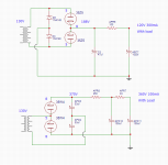
Attached is a quick draw up of what I am trying to do, the numbers may be off a bit, I'm still testing things, but it pretty close. The plan is to run both of these circuits off a 500mA 115:120 transformer that out puts 130VAC. The mono block tube amp will use 25L6 tubes with 35Z5 or 35W4 rectifiers. The heaters will string serial 120VDC 300mA. The 25L6s will run PP on the 360V 180-0-180 at 50mA. Not sure exactly how I will split the 360V (There is a center tap on the secondary) or get the phase split yet but starting with the power supply. I just wanted to make sure that running the power like this off a single secondary would work.
Attachments
There is a general rule in electronics: two things cannot be both connected and separated. A corollary of this rule is that only in quite limited circumstances can you run two PSUs from one secondary.
I think you will find that if you try to combine those two circuits you will need some things both connected and separated.
I think you will find that if you try to combine those two circuits you will need some things both connected and separated.
That's your intended load? 120V 300mA and 360V 100mA?
That's awkward. HIGH currents (too high for 35Z5!) and both similar Watts.
Your 120V 0.3A is a 400 Ohm equivalent load. 30-50ufd is much too small. Ripple will be huge. Yes you have another stage of filter, but don't give it boulders. I pencil 1uFd/mA, which suggests hundreds of uFd.
You *can* take DC off the midpoint of that doubler. (Looks strange, but it works. While the AC is tied there, the other side of the AC is flying around, this end can stay steady.)
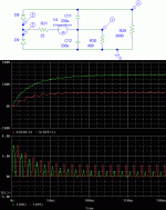
Using big caps, and crystal diodes, and an estimate of winding resistance, I get these curves.
The peak rectifier current is 2.3A, far past the 0.6A rating of 35Z5.
Increasing winding resistance or decreasing caps does reduce peak current but then your DC voltages are even further off what you want.
That's awkward. HIGH currents (too high for 35Z5!) and both similar Watts.
Your 120V 0.3A is a 400 Ohm equivalent load. 30-50ufd is much too small. Ripple will be huge. Yes you have another stage of filter, but don't give it boulders. I pencil 1uFd/mA, which suggests hundreds of uFd.
You *can* take DC off the midpoint of that doubler. (Looks strange, but it works. While the AC is tied there, the other side of the AC is flying around, this end can stay steady.)
Using big caps, and crystal diodes, and an estimate of winding resistance, I get these curves.
The peak rectifier current is 2.3A, far past the 0.6A rating of 35Z5.
Increasing winding resistance or decreasing caps does reduce peak current but then your DC voltages are even further off what you want.
Attachments
Last edited:
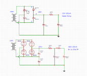
If you want to explore how it might work, you need to draw one circuit containing the two PSUs driven from one secondary. You will probably find that there is a short across one or more diodes, or possibly across the secondary. Drawing two separate circuits while mentally remembering that there is only one secondary will hide whatever problems there are.
As far as output power, lets say I need 20mA and I have 2 tube diodes that put out 10mA each and they are in full wave config so each is putting out 10mA while the other is off does that mean I need 4 instead of 2 or does the filter cap compensate for this and I only need 2 or is it something that there is a formula for. Like AC to DC after filter is source x 1.414?
Let me put it another way, if I have two tube diodes that put out their max of 10mA that is 20mA. After the filter the circuit on the other end needs 20mA. I wont have 20mA available will I? I would need more diodes or bigger ones. The out put be .7 of the 20mA. RMS like voltage? Theoretically without the load consideration. Is there a general rule about this when considering the diode to use?
That is the least of your problems.
You keep drawing two separate circuits, which while separate may work, sort of, but since post #1 you claim they will be used together.
You keep drawing TWO secondaries, and verbally claiming they are one.
OK, repeat your drawing with **ONE** secondary, connected at the same time to BOTH rectifir/capacitor packs and see for yourself.
Waiting for the proper drawing.
Discussing your circuit is pointless until you do so.
By the way, what DF96 asked too.
I don't understand this statement. As we keep saying, draw us what you think will work. Don't draw something different.Blaxshep said:Let me put it another way, if I have two tube diodes that put out their max of 10mA that is 20mA.
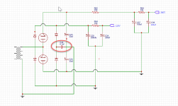
Ok, lets start with the parallel circuit issue. I have drawn a circuit that actually has both in one as was asked. I think I see the problem now. I would need a cap (Circled in red) to keep the voltage divider DC off the bridge on the parallel circuit. Does this circuit look like it would work?
The secondary is putting off 130VAC at 500mA, I may still have to tweek the PI filter resistors to get the desired output but from experiment those values are close. Heater string requires 120VDC 150mA. The B+ 360VDC Circuit only requires 100mA.
The secondary is putting off 130VAC at 500mA, I may still have to tweek the PI filter resistors to get the desired output but from experiment those values are close. Heater string requires 120VDC 150mA. The B+ 360VDC Circuit only requires 100mA.
Attachments
I think you'll find that both circuits won't share the same 0V ground.
You might be better to construct a buck convertor instead of a doubler in order to provide the increased voltage.
You might be better to construct a buck convertor instead of a doubler in order to provide the increased voltage.
I think you'll find that both circuits won't share the same 0V ground.
You might be better to construct a buck convertor instead of a doubler in order to provide the increased voltage.
I did think about that, couldn't the grounds be not connected to each other, individually floating for lack of a better term?
I dont know anything about Buck converters, looks like just a diode cap and choke, but I'm sure it has to be more complicated that that. Ill look into it. What would be the advantage?
Doublers tend to shift the 0V point which would be a problem if you are you using the same windings for a different supply.
There is nothing wrong with using the same windings for different supplies but the reference 0V must be the same for all supplies.
Do a little bit of homework on buck convertors. Most advertised circuits will be for low voltage convertors but the technique is the same at higher voltages.
There is nothing wrong with using the same windings for different supplies but the reference 0V must be the same for all supplies.
Do a little bit of homework on buck convertors. Most advertised circuits will be for low voltage convertors but the technique is the same at higher voltages.
Last edited:
- Status
- Not open for further replies.
- Home
- Amplifiers
- Power Supplies
- Transformer secondary parallel out question