Hello:
I have read quite a few internet articles and threads on the subject of transformer arrangement for minimizing hum. I am finalizing my layout for a current monoblock tube amplifier build.
It seems that the most common advice is to 'arrange the OPT and PT at 90 degrees to one another'. However, it has never been clear to me which exact axes of the OPT and PT are supposed to be orthogonal to one another in this recommendation.
(Bad link removed, see below in reply no. 7 where I inserted the pics)
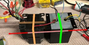
In any event, I did the 'headphone test' with this transformer pair. Referring to the photo I have posted here, the quietest arrangement I found is the position almost shown in the attached photo. The qualifier 'almost' is applied here as they are shown turned upside down about the axis sketched in red, so in the photo we are viewing them from the bottom. Note that in this (quiet) arrangement, the orientation of the plate stacks in both transformers (solid orange and green lines), are parallel to one another. This surprises me as it seems to run contrary to the common advice to arrange 'OPT and PT at 90 degrees to one another'.
If I rotate the PT 90 degrees so it's plate stack becomes parallel to the dashed orange line, the noise level jumps significantly higher. Rotating the OPT 90 degrees relative to the orientation indicated by the green line has little or no effect. It might be slightly noisier in that position than the orientation indicated. If so, the difference is imperceptible - to my ear anyway. My DVM set on AC volts cannot measure any difference between these two OPT orientations.
Does this make any sense? I prefer the orientation shown as it is significantly better from a chassis construction standpoint, but considering the overwhelming prevalence of statements recommending 90 degrees of relative rotation I am uneasy with this choice. Does anyone have any insight or advice to give?
As usual, any advice is much appreciated.
Best regards,
David
I have read quite a few internet articles and threads on the subject of transformer arrangement for minimizing hum. I am finalizing my layout for a current monoblock tube amplifier build.
It seems that the most common advice is to 'arrange the OPT and PT at 90 degrees to one another'. However, it has never been clear to me which exact axes of the OPT and PT are supposed to be orthogonal to one another in this recommendation.
(Bad link removed, see below in reply no. 7 where I inserted the pics)
In any event, I did the 'headphone test' with this transformer pair. Referring to the photo I have posted here, the quietest arrangement I found is the position almost shown in the attached photo. The qualifier 'almost' is applied here as they are shown turned upside down about the axis sketched in red, so in the photo we are viewing them from the bottom. Note that in this (quiet) arrangement, the orientation of the plate stacks in both transformers (solid orange and green lines), are parallel to one another. This surprises me as it seems to run contrary to the common advice to arrange 'OPT and PT at 90 degrees to one another'.
If I rotate the PT 90 degrees so it's plate stack becomes parallel to the dashed orange line, the noise level jumps significantly higher. Rotating the OPT 90 degrees relative to the orientation indicated by the green line has little or no effect. It might be slightly noisier in that position than the orientation indicated. If so, the difference is imperceptible - to my ear anyway. My DVM set on AC volts cannot measure any difference between these two OPT orientations.
Does this make any sense? I prefer the orientation shown as it is significantly better from a chassis construction standpoint, but considering the overwhelming prevalence of statements recommending 90 degrees of relative rotation I am uneasy with this choice. Does anyone have any insight or advice to give?
As usual, any advice is much appreciated.
Best regards,
David
Last edited:
1. Your photo did not post.
2. Not only is the orientation of the power transformer, B+ choke, interstage transformer, and output transformer important . . .
Do not use a Magnetic Steel Chassis.
Magnetic steel conducts magnetic fields really well; just as well as copper wires, silver wires, and gold wires conduct electricity.
3. Spacing of interstage transformers, and output transformers to the power transformer and to the choke is important.
Using an Aluminum chassis, the magnetic coupling of interference tends to go to the square of the distance.
4 inch spacing versus 2 inch spacing will reduce the interference by 4X.
Last edited:
You should read a quick article on "The Right Hand Rule", then pop covers off any iron you have if you're uncertain about how the coils are wound.
Depending on the transformers, popping the covers off can disturb the laminations.
In some cases it can disturb the spacing of the Es and the Is in a single ended output transformer.
It can also make for a humming sound on a power transformer, or a choke, and can make for "talking" the music on an output transformer.
For a single ended output transformer that has laminations that are Es and Is, there is an Air Gap. You will see a line between the Es and the Is.
The E has a two spaces in it for the coil(s).
The Es have the coils wrapped around them over the center, not the outside.
A B+ Choke also has an air gap, and the coil is wrapped around the center of the Es.
A power transformer, has the Es and the Is interleaved, E, then I, then E, then I, then E . .
The coils are wrapped around the spaces in the Es. Instead of one line at an Air Gap, you will see broken lines, as the Es and Is are interleaved. Knowing the nature of the laminations and their orientation will now show you how the coils are wound.
You may have to look at some pictures of transformers, and their assembly to see what I am talking about.
Someone once said, a picture is worth 1000 words.
You want the coils of the output transformers to be at right angles (90 degrees) to the coils of power transformers and chokes.
A magnetic steel chassis will mess all this up, and the best angle may be something other than 90 degrees, but it can not be very good (don't ask me how I know).
Generally, Interstage transformers and single ended output transformers are the most sensitive to magnetic pickup.
Push pull output transformers have the Es and Is interleaved, so they are less sensitive to magnetic pickup.
Last edited:
Thank you for the responses. Sorry about the bad link.
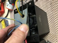
I added a 2nd picture where I lift the bottom cover. Not very clear but you can see the plate stack in the center.
Best regards,
D
I added a 2nd picture where I lift the bottom cover. Not very clear but you can see the plate stack in the center.
Best regards,
D
Attachments
Last edited:
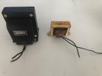
This will be a choke input filter. The massive choke on the left (10 H) is almost as big as the PT. The plan is to locate that pretty far from the PT, plates at 90 degrees to PT plates. That location is even farther from the OPT.
Not worried about the 2.5 H choke so much because it will be down below inside the chassis, which will be in wood BTW, with an aluminum top plate.
Not worried about the 2.5 H choke so much because it will be down below inside the chassis, which will be in wood BTW, with an aluminum top plate.
Attachments
Don't worry about coupling from the power transformer to choke (unless it's a second choke feeding low level stages). But power supply choke (especially choke input) can couple to audio transformers.
6A3Summer
Can you offer an explanation why Single ended OPTs may be more prone to induced hum?
Or rather, why a gapped transformers is more prone, than a non gapped one
Its something that I havent read before
Is it just the more efficient coupling of windings and core?
Can you offer an explanation why Single ended OPTs may be more prone to induced hum?
Or rather, why a gapped transformers is more prone, than a non gapped one
Its something that I havent read before
Is it just the more efficient coupling of windings and core?
Last edited:
mondogenerator,
Let's build one common form of transformers:
Use E laminations, and I laminations.
An E has three open ends.
The E has a top and bottom end; and it has a middle end.
Wrap a coil around the middle end, that is between the top end and the bottom end.
That forms both a magnetic pickup, and a electromagnet (a reversible device).
Now, put a non-magnetic spacer over the three ends of the E. Thin Cardboard, paper, plastic tape, etc.
Then, put an I over the non-magnetic spacer, that covers the area on the other side of the spacer (the three open ends of the E).
That is a single ended transformer with an air gap (non-magnetic spacer).
All the Es are on one side of the non-magnetic spacer, and all the Is are on the other side of the non-magnetic spacer.
There are spaces and magnetic poles to this transformer.
At the spacing, the I and the E are different magnetic poles.
Ready to Radiate magnetic fields, and ready to Pick up magnetic fields (again, reversible).
Now, build a different transformer:
Instead, Overlap and alternatively Interleave the E laminations and the I laminations.
Think of a 3 as an E (just a left facing "E" and a right facing E).
E, I, 3, I, E, I, 3, I, E, I, 3, I, etc.
These are Overlapped and Interleaved laminations.
There is no non-magnetic spacer (no air gap).
This is one form of a push pull transformer.
Now, where is the air gap spacing? It is not there.
Where is the place for the magnetic field to easily get out.
Where is the place for an external magnetic field to easily get in?
The transformer is less sensitive to external magnetic fields.
The overlapped E-I transformer does not radiate as much magnetic field, either.
A Power transformer is constructed like a push pull transformer.
It does not have a spacer (air gap).
A DC choke is constructed like a single ended transformer.
It has the spacer (air gap).
I hope that explains it.
Last edited:
in a single ended traffo, we deal with two types of flux, the flux induced by the winding to the core and the dc flux at the air gaps owing to the dc currents flowing in one direction only...such consideration is not present with a push pull output traffo...
- Home
- Amplifiers
- Tubes / Valves
- Transformer arrangement question