Hello,
I have made a nice TPA3122 amplifier, but still on breadboard right now. It works perfekt with my batterypack.
When I use it on my supply it start clicking like it's turning on and off all the time.
I have 2 x 2 4700uF capacitors(2 pairs in serial connection) on the supply and 2 x 470 uF on the breadboard.
Do I need to add something for more stabelised supply?
Thank you,
Simon H.A.
It's rated 18VAC @ 2,78A and when converted to dc it is at 27V no load.
My supply is a transformer, dual primaries and secondaries in serielconnection.
My supply is a transformer, dual primaries and secondaries in serielconnection.
But what are the battery and the power supply voltages? The latter may be too high.
Also, it could be an EMI issue.
Also, it could be an EMI issue.
Batteri is at 22V fullcharged. As I said the supply is 27V DC. The chip is rated for a maximum of 36Volt.
What does EMI stand for?
What does EMI stand for?
Hm... I have charged my batterypack and now it also start clicking when I turn up for the volume.
Regards,
Simon H.A.
Regards,
Simon H.A.
I think it's stability problems since it sometimes on high volume first start the clicking thing and then it start making a high pitch noise and wont stop until I turn the volume down or disconnect power and connect again.
So I have made a pcb layout. I have added 2 x10uF and 2 x 100uf elecrolytic in serial-connection, because I think it could help with the stability and it also provides the speakerground.
I would be pleased if you could give some feedback on my layout. I'm willing to change the whole layout if it will give me better results since this project means a lot to me.
Thank you,
Simon H.A.
Attachments

I think it's stability problems since it sometimes on high volume first start the clicking thing and then it start making a high pitch noise and wont stop until I turn the volume down or disconnect power and connect again.
So I have made a pcb layout. I have added 2 x10uF and 2 x 100uf elecrolytic in serial-connection, because I think it could help with the stability and it also provides the speakerground.
I would be pleased if you could give some feedback on my layout. I'm willing to change the whole layout if it will give me better results since this project means a lot to me.
Thank you,
Simon H.A.
hey simon
i think you have missed out on the out put inductor in series with a electrolytic capacitor, on the out put side,
and your two grounds are to be made one at one point so have alook in to it,
i mainly feel its your dc blocking caps and the inductors that are missing. check the datasheet diagram properly,
if you want to try i have some design , let me know if you want to make the pcb i will mail you the desing i havent tried it so cant say and its from a fellow on the forum
Hi sexya,
I have output inductors, I just think you are mistaking them as a capacitor, but they are 47uF inductors and they are marked with the letter "L" for inductor.
I haven't quite yet understood why the groundings for the LC filter also must be connected to negative supply. Isn't it supposed to filter both positive and negative signals since audio is AC? or does it still do its job with negative as ground?
Regards,
Simon H.A.
On your PCB layout you have the upper right most 470uF cap straddling two grounds that aren't even connected together.
Last edited:
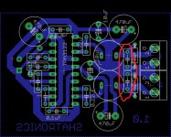
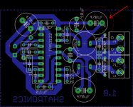
No. It's the one with the arrow pointing at it in the below pic.
You have it's + side connected to the output ground and its - side connected to the input ground. The input and output grounds are not connected anywhere on the layout.
EDIT: Same goes for the 10uF next to it.
I would get rid of both of those caps and connect the two grounds at that point. Also, as previously stated, you don't have any DC blocking caps in series with the output (unless you plan to add them externally).
Attachments
Last edited:
lol I was dumb right there.
So actually it is the best not to have any of these on the pcb? So I should just have the speakers connected to the speakerground from my powersupply?
Here is a new layout where the filter is connected to the negative supply, is it correct now?
Edit:
I will also add the DC blocking caps. Does they also improve the performance?
Attachments
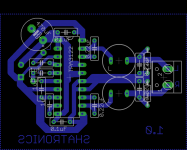
I'm not an expert on grounding (or anything for that matter), but I would put the ground connecters back on the PCB like you had them. You have room to put the two output caps next to the inductors connected in series.
Sorry, I'm getting some of what you say, but could you maybe draw it for me so I'm totally sure of what you mean?
Regards,
Simon H.A.
Regards,
Simon H.A.
Where is the double sided PCB with a good ground plane and the ceramic SMD decoupling caps? This is class D, no TDA2030 😉 the difference between working or not working may be just some PCB track and capacitor lead parasitic inductance 😛
Sorry, I'm getting some of what you say, but could you maybe draw it for me so I'm totally sure of what you mean?
Sorry, I don't have time at the moment. It's all right there in the datasheet though. Take a look at figure 28.
Maybe looking over the evaluation module datasheet will help you out some as well.
http://focus.ti.com/lit/ug/slou214a/slou214a.pdf
I get it all now how it works.
Thanks to you all for using your time to help me.
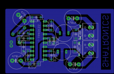
I have created a new layout and I will try make it and just cross my fingers for that it is stable.
I have made a good ground plane now, and I really like this new layout. I think it will be stable with this board layout.
Thanks a lot for all the help everyone, this forum is very nice.
Regards,
Simon H.A.
Thanks to you all for using your time to help me.
I have created a new layout and I will try make it and just cross my fingers for that it is stable.
I have made a good ground plane now, and I really like this new layout. I think it will be stable with this board layout.
Thanks a lot for all the help everyone, this forum is very nice.
Regards,
Simon H.A.
Attachments
- Status
- Not open for further replies.
- Home
- Amplifiers
- Class D
- TPA3122 works fine on battery - starts clicking on powersupply.