I followed the reference design. But don't know why the circuit is not working. Can you put your opinion why the design is not working ?
When I power up the circuits, R12 (10 ohms) is getting very hot and starts smoking and the whole circuits take almost 1.1 Amp without any load.
When I power up the circuits, R12 (10 ohms) is getting very hot and starts smoking and the whole circuits take almost 1.1 Amp without any load.
Attachments

There's no other way for current to flow through R12 except through C29, unless you've got something shorted or messed up with your layout.
I further investigated and didn't find any short in the layout. and discovered that R8, R12, R14 and R17 all are heating up ! It seems C20, C29, C33 and C43 are not shorted , but when I power the board they gets shorted ! Strange !
Take a picture of your build. Also verify the cap value is what you think it is, eg. you didn't mistake pf for nf.
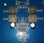
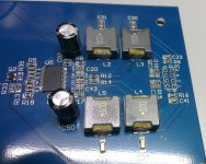
Attached is the picture of my PCB. I didn't use any load.
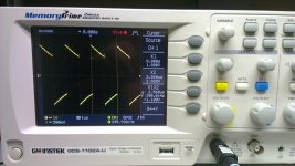
I also powered the board with 5V power supply and observe the waveshape across the R8, R12, R14 and R17 resistors. It seems that they are oscillating at 390 Khz rate. Thats why current is flowing through the resistors and heating up.. Whats the reason of this oscillation ?
I also powered the board with 5V power supply and observe the waveshape across the R8, R12, R14 and R17 resistors. It seems that they are oscillating at 390 Khz rate. Thats why current is flowing through the resistors and heating up.. Whats the reason of this oscillation ?
Attachments
Always have a load on the amp when powered. Damage may occur if not loaded.
To reduce noise pickup without drive have a 1K or lower on the inputs.
The "oscillation" is the 400KHz switching frequency.
To reduce noise pickup without drive have a 1K or lower on the inputs.
The "oscillation" is the 400KHz switching frequency.
Always have a load on the amp when powered. Damage may occur if not loaded.
To reduce noise pickup without drive have a 1K or lower on the inputs.
The "oscillation" is the 400KHz switching frequency.
How can I prevent the oscillation without load ? As the scenario is such that their may not be load present when I turn on the amp.
Do you mean to use a 1k resistor to pull down the input just after input cap ?
How can I prevent the oscillation without load ? As the scenario is such that their may not be load present when I turn on the amp.
You use MUTE. It really doesn't prevent the "oscillation" as such but it's not present on the outputs when muted.
If you really want to kill the "oscillation", you turn off the amp. As said the "oscillation" is the switching frequency and as such the basis of the working principle of a class D amp. If you don't want it, build a class AB amp instead.
Last edited:
...
Do you mean to use a 1k resistor to pull down the input just after input cap ?
No
At the point you would normally connect your music source...the input.
You use MUTE. It really doesn't prevent the "oscillation" as such but it's not present on the outputs when muted.
If you really want to kill the "oscillation", you turn off the amp. As said the "oscillation" is the switching frequency and as such the basis of the working principle of a class D amp. If you don't want it, build a class AB amp instead.
Thanks for the info.
But I have seen couple of Class D car amps, powered without connecting speaker. So there might be some kind of mechanism to damp the oscillation. How can I do that ?
You cannot damp the switching frequency.
You can however have a load detection circuit that pull to MUTE until a load is detected.
You can however have a load detection circuit that pull to MUTE until a load is detected.
Class d like a load connected.
I found with the irs2092 class d IC I got two modes occurring with no load.
1/ Output sat at +17VDC.
Or:
2/ 2092 oscillated but fried output filter capacitor due to output choke ringing.
I found with the irs2092 class d IC I got two modes occurring with no load.
1/ Output sat at +17VDC.
Or:
2/ 2092 oscillated but fried output filter capacitor due to output choke ringing.
Take a picture of your build. Also verify the cap value is what you think it is, eg. you didn't mistake pf for nf.
I made mistake in the cap value. it was .33nF and my cap was .33uF ! I replaced them and they are no heating up issues.
And I dont see any problem without load now. It seems ok and idle current is 100mA. 🙂
100mA looks pretty much idle current to me.
At 12V= input I measured about 30mA with the TPA3118 board that I have designed: mono/PBTL-mode, Output filters are 2x10uH/0.68uF
At 12V= input I measured about 30mA with the TPA3118 board that I have designed: mono/PBTL-mode, Output filters are 2x10uH/0.68uF
100mA looks pretty much idle current to me.
At 12V= input I measured about 30mA with the TPA3118 board that I have designed: mono/PBTL-mode, Output filters are 2x10uH/0.68uF
100mA was in fact the total board current (the board has some other circuitry) at 24V.(So actual amp current is around 65mA)
You cannot damp the switching frequency.
You can however have a load detection circuit that pull to MUTE until a load is detected.
Or do diode-clamping the outputs to VCC/GND.
- Status
- Not open for further replies.
- Home
- Amplifiers
- Class D
- TPA3118D2 is not working