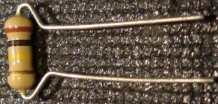
I got PCB board for DIY assembling, so I need purchase components to start PCB assembling. PCB size 66 x 60mm (2.6”x2.36”), through-hole mounting. Unfortunately, PCB layout isn't well-designed, especially resistors. The spec noted all resistirs are 1/8W, but based on Digikey part # they are 1/6W. Main problem is that all holes for resistors have 5mm spacing. Even for 1/8W resistors its too tight, and afaik, min spacing for 1/8W is 7.5mm. I didn't find any hand component lead bending tool that have 5mm distance to lead bend. All starts from 7.5mm. I like the neat and accurate assembly.
Can someone advice?
Can someone advice?
if you can't mount them horizontally, try the vertical option.
Like this:
Mount a resistor upright standing - TARGET 3001! PCB Design Freeware is a Layout CAD Software|Support, Tutorials, Shop
Like this:
Mount a resistor upright standing - TARGET 3001! PCB Design Freeware is a Layout CAD Software|Support, Tutorials, Shop
This standard table tells me that:
But if your bending plier can´t, you´ll have to bend them by hand.
No big deal 😉
so 5mm spacing is ample for 1/8 Watt resistors.Power rating......Body length (l)
Watt................mm
1/8 (0.125).......3.0
Read more Resistor Sizes and Packages >> Resistor Guide
But if your bending plier can´t, you´ll have to bend them by hand.
No big deal 😉
Depend on manufacturer, but not 3mm:
CF18JT3K30TR-ND
for 0.125W, 1/8W: body length 3.30mm ± 0.30
3.3KEBK-ND
for 1/6W: body length 3.4±0.3mm
For 5mm holes spacing, too small distance from the part body to the start of the bend. (can be unsafe?)
Vertical mounting is possible, but didn't find any simple hand bending tool for axial components vertical mounting.
Last edited:
Vertical mounting is possible, but didn't find any simple hand bending tool for axial components vertical mounting.
You already have the tools you need...they're called "fingers." 😉 Just bend them over and stick them through the holes.
Mike
if you can't mount them horizontally, try the vertical option.
Like this:
Mount a resistor upright standing - TARGET 3001! PCB Design Freeware is a Layout CAD Software|Support, Tutorials, Shop
Alternately offset them too.
First one with body on then next with body on the left.
Depend on manufacturer, but not 3mm:
CF18JT3K30TR-ND
for 0.125W, 1/8W: body length 3.30mm ± 0.30
3.3KEBK-ND
for 1/6W: body length 3.4±0.3mm
For 5mm holes spacing, too small distance from the part body to the start of the bend. (can be unsafe?)
Vertical mounting is possible, but didn't find any simple hand bending tool for axial components vertical mounting.
You are overthinking it.
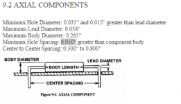
I've attached an excerpt from a 'board manufacturing guidelines' document I have to hand.
The general recommendation for thru-hole parts hole spacing is: Body Length + 1.27 mm
So take your 1/6 watt for example:
Hole spacing = Body Length + Max Tolerance + Guideline length
3.4mm + 0.3mm + 1.27mm = 4.97mm
So 5mm is perfectly fine.
Attachments
For 5mm holes spacing, too small distance from the part body to the start of the bend. (can be unsafe?)
Vertical mounting is possible, but didn't find any simple hand bending tool for axial components vertical mounting.
For tidy bends when mounting the resistors vertically you need a screwdriver or similar shaft with a diameter of your spacing (5mm) less one hole diameter (0.8mm at a guess) so about 4mm. Just roll the lead 180deg round this for a nice smooth radius bend. Also if you need a test point maku sure the bend is on the correct side of the resistor to use this top bend/loop to get a test probe on easily.
You are overthinking it.
I've attached an excerpt from a 'board manufacturing guidelines' document I have to hand.
The general recommendation for thru-hole parts hole spacing is: Body Length + 1.27 mm
So take your 1/6 watt for example:
Hole spacing = Body Length + Max Tolerance + Guideline length
3.4mm + 0.3mm + 1.27mm = 4.97mm
So 5mm is perfectly fine.
So, we can bend the resistor right near the body, without radius, not worrying about possible chipping of the enamel?
Didn't find any manufacturer that offer resistor lead Bending Tool that support 5mm spacing. For example, even Model 802 support Bend Range 0.26" to 1.10"
So, we can bend the resistor right near the body, without radius, not worrying about possible chipping of the enamel?
Yes it has been done this way successfully since resistors first went through holes.
The metal leads on a resistor are quite malleable and will bend to shape very easily. Sharp radii are no problem. Repeated bending is obviously not good but honestly, it is as simple as pick up resistor - bend - poke through holes - solder - repeat.
As explained, you are well within design specifications. Once the resistor is in, bent, placed against the board and soldered, it is mechanically stable.
Didn't find any manufacturer that offer resistor lead Bending Tool that support 5mm spacing. For example, even Model 802 support Bend Range 0.26" to 1.10"
Seriously, you don't need a tool.

- Status
- Not open for further replies.
- Home
- Design & Build
- Parts
- Too too tight spacing for resistors on PCB