hi!
Here is my own idea.
It is very useful when testing building amplifiers.
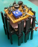
Adjustable TO3 Active PowerResistor
Some details:
- Like 10-50 Ohm
- Max power ~20 Watt
- Discrete transistors Op-amp as comparator
- Compares adjustable reference leg, including potentiometer
- with TO3 power leg, including one 1 Ohm power resistor
Connections:
- RED +voltage
- BLACK 0 Volt
- GREY current sense, gives a reading 1.00 Volt for 1.00 Ampere
Enjoy and build the same yourself.
Mine is for DC applications.
Was originally used, to see how much a transformator voltage
would drop at different load.
Used as variable load resistor.
Next project could be for alternate current, AC.
Which could be more useful for some amplifier testings.
Here is picture:
Here is my own idea.
It is very useful when testing building amplifiers.
Adjustable TO3 Active PowerResistor
Some details:
- Like 10-50 Ohm
- Max power ~20 Watt
- Discrete transistors Op-amp as comparator
- Compares adjustable reference leg, including potentiometer
- with TO3 power leg, including one 1 Ohm power resistor
Connections:
- RED +voltage
- BLACK 0 Volt
- GREY current sense, gives a reading 1.00 Volt for 1.00 Ampere
Enjoy and build the same yourself.
Mine is for DC applications.
Was originally used, to see how much a transformator voltage
would drop at different load.
Used as variable load resistor.
Next project could be for alternate current, AC.
Which could be more useful for some amplifier testings.
Here is picture:
Attachments
here
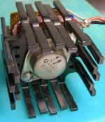
You can see how I attached TO3 at bottom.
I have used some isolation material between
control circuit and power transistor.
Gives a little both electrical and temperature separation.
Power transistor is a TO3 BUX39
which I from some old electrical junk I have found and carried home.
For free, of course!
Same goes for the small signal transistors.
They are taken from old circuits - reused.
Attachments
How difficult is the principle of comparingjanneman said:Well, it would be difficult for us to built it if we don't have the schematic 😉
Jan Didden
a reference current with the power current?
It is of no more hardship, than comparing a reference voltage
with a 2 resistor voltage sense, like when using Voltage regulator.
Of course for all those not familiar with this technique
there is a very small amount of basic op-amp knowledge to find out.
🙂 If I had the schematic, I would help you and post it today
janneman.
But this is an old circuit I built maybe 10 years ago.
My papers used to calculate and design this circuit
are somewhere in some pile of papers somewhere in my stuff.
If they arent thrown away.
From my photo, some clever and more experienced diyaudio member, that really understands my concept,
may easily get the circuit, including most resistor values.
I remember I tried to make the circuit only have some % current consumption compared to total,
to make the current sense (GREY wire) be reasonably correct.
And so give a good value for actual resistance, in Ohm.
R = Voltage across circuit / Current
The current sense, as told above, gives a reading 1.00 Volt / 1.00 Ampere.
regards
lineup
Wow.
Waiting ten years to publish.
Talk about "hiding your light under a bushel".
You would never survive in academia.
Waiting ten years to publish.
Talk about "hiding your light under a bushel".
You would never survive in academia.
lineup said:
How difficult is the principle of comparing
a reference current with the power current?[snip]
I'm sure what your purpose is with these posts. Do you really expect people to look at your pictures, saying 'wow, I need that' and rushing out to built it too? How would they do that?
Jan Didden
😉
I see.
No problem, okay.
Otherwise, I am a bit lazy, you see
and I already have a working active power resistor circuit
so my motivation for building another one is = 0, zero.
Anybody who would like to have this
and think it would be of help and use
will find out and build.
Some even better more versatile circuit than mine, most probably.
The basic concept and idea will be just about the same.
Like for other active loads, pure resistive or not. It is nothing new.
My topic is to show how one can do.
Present the idea of using a variable PowerResistor.
Somebody surely can benefit from this topic.
==================================
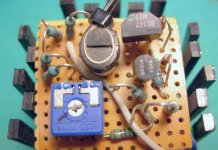
For hobby designers willing to do some work of their own ( not for copy-cats )
this third image might be helpful, too
I see.
No problem, okay.
Otherwise, I am a bit lazy, you see
and I already have a working active power resistor circuit
so my motivation for building another one is = 0, zero.
Anybody who would like to have this
and think it would be of help and use
will find out and build.
Some even better more versatile circuit than mine, most probably.
The basic concept and idea will be just about the same.
Like for other active loads, pure resistive or not. It is nothing new.
My topic is to show how one can do.
Present the idea of using a variable PowerResistor.
Somebody surely can benefit from this topic.
==================================
For hobby designers willing to do some work of their own ( not for copy-cats )
this third image might be helpful, too
Attachments
I don´t get why you use comaprator, when you need linear regulation, not two-state regulation. Can you explain?

Hi,
if the AC statement is true then he really has been
if the AC statement is true then he really has been
"hiding your light under a bushel".
janneman said:
I'm sure what your purpose is with these posts. [snip]
I meant to say, "I'm not sure what.... Sorry.
I still am not.
Jan Didden
BTW how can you make a comparator with just three transistors?
I guess you meant something like differential stage, am I right?
I guess you meant something like differential stage, am I right?
Hi!
I am sorry but I don't get this either.
Why not a schematic?
If you have construction in hand it must to be easy to draw a schem, especially if you designed it.
I am sorry but I don't get this either.
Why not a schematic?
If you have construction in hand it must to be easy to draw a schem, especially if you designed it.

- Status
- Not open for further replies.
- Home
- Amplifiers
- Solid State
- TO3 Active PowerResistor - variable