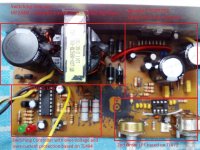
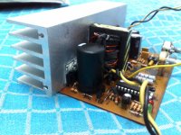
Hi! Just made four car amps based on TDA7294 (first pic). Two of them are OK, but at the other two, I noticed that the controller IC TL494 gets hot and doesn't work at all.
IC is fine, as I tested the whole 4 circuits with that. The problem must be somewhere in the circuits, but I have no clue where it might be. I did some measurements and got confused by the results:
--There is no current draw from B+ line and switching transistors are cold.
--I have a current draw of 270mA across the REMOTE line (TL494 supply), which is too much IMHO. The healthy circuit draws only 30mA.
--I have a 0.8V pulse, plus an offset voltage of 0.4V at the output pins (going to the switching transistors). The healthy circuit gives 9VAC + 5VDC at those pins.
--When I turn the circuit ON, for near 2 seconds the IC temperature is OK, although it doesn't work. After 2sec, the IC starts to heat up like crazy.
--Control Circuits include voltage drop protection (under 9V), over-voltage protection (adjustable, near 15V) and over-current protection. None of the protections are activated in the damaged circuits, meaning there's no over-voltage, over-current or under-voltage,- obviously.
I suspect something must be wrong with the error amplifiers (due to the voltage test), but the whole parts connected to the error amps' pins were OK and identical to the healthy circuit, as far as I tested.
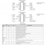
I posted the voltages across the pins of IC (pic 4), the schematic, and the PCB layout if any helpful.
I'm not an expert (yet). I read the TL494 datasheet but understood nothing out of it. Any simple definition of what's going wrong here is helpful and highly appreciated.
Any comments are welcome.
++PS: This SMPS has no feedback voltage for PWM adjustments, so what are the error amps used for?
Regards,
Ali
IC is fine, as I tested the whole 4 circuits with that. The problem must be somewhere in the circuits, but I have no clue where it might be. I did some measurements and got confused by the results:
--There is no current draw from B+ line and switching transistors are cold.
--I have a current draw of 270mA across the REMOTE line (TL494 supply), which is too much IMHO. The healthy circuit draws only 30mA.
--I have a 0.8V pulse, plus an offset voltage of 0.4V at the output pins (going to the switching transistors). The healthy circuit gives 9VAC + 5VDC at those pins.
--When I turn the circuit ON, for near 2 seconds the IC temperature is OK, although it doesn't work. After 2sec, the IC starts to heat up like crazy.
--Control Circuits include voltage drop protection (under 9V), over-voltage protection (adjustable, near 15V) and over-current protection. None of the protections are activated in the damaged circuits, meaning there's no over-voltage, over-current or under-voltage,- obviously.
I suspect something must be wrong with the error amplifiers (due to the voltage test), but the whole parts connected to the error amps' pins were OK and identical to the healthy circuit, as far as I tested.
I posted the voltages across the pins of IC (pic 4), the schematic, and the PCB layout if any helpful.
I'm not an expert (yet). I read the TL494 datasheet but understood nothing out of it. Any simple definition of what's going wrong here is helpful and highly appreciated.
Any comments are welcome.
++PS: This SMPS has no feedback voltage for PWM adjustments, so what are the error amps used for?
Regards,
Ali
Attachments

error amps are used for low-v detection and over-v detection (the one with the pot).
hot 494 possibly means overloaded / shorted outputs E1, E2.
I'd check whatever connects to the 494 outputs E1 and E2, PCB/solder short between E1- E2 or anywhere near, reversed diodes 4,5,12,13, reversed transistors t1,t3
ohm meter between E1-E2, and E1-gnd, E2-gnd should read .5 to 1k ohm, if much lower, trace it ...
- Status
- Not open for further replies.