I was designing a part of my power supply when I was running trough the datasheet and the basic application notes of the TL431 and I found two images that particularly interested me.
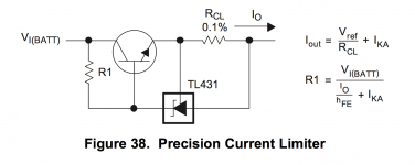
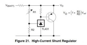
One is a "precision shunt regulator" and the other one is a "precision current limiter".
Firs I want to talk about the current limiter. its essentially a really good constant current source or sink when you use it that way. Its a two wire contraption and it fits perfectly into old tube amplifiers as a CCS to directly replace a resistor because its a two wire device. Doesnt need any power to power a op amp none of that nonsense.
I know its not as easy a a depletion mosfet cascode or a speciffic component meant for CCS. Most of the CCS components are limited with minimum current 8mA and the voltage and so on. (the IXS something something part number if you look in its datasheet more in depth the limmitation is there. Doesn't mean it wont work but its not ideal or bordeline stable)
This could basically work with practically anything. the TL431 is not dependant on the voltage across the entire device so you dont fry it not even if you were to put 600V across it because all the work would have been done in the transistor(dont take this literary because it does not work below 2.5V and some current to open the transistor so there is a lower limit to this). You can put this in the anode or the cathode of any tube. You just need to do some little math to figure the resistor values and voila got your 100% accurate current source / sink.
The second image is the shunt regulator. This one interested me because of a other topic here on the forum where we discussed instabillity caused by drifting bias on the cathode resistor at high loads. I realised we can use the 431 as a shunt regulator so we can set the bias of the tubes on a cathode biased amplifier just like we would in a fixed bias enviroment.
Trained eyes that know something about the 431 would relise that even a EL34 amp like the mullard 5-20 would exceed the voltage capabillity of the 431 (I found the bias voltage on 470R resistors with mine at 450V B+ to be 35-37V and the 431 is maxed in 33). Simple solution put a 15V zener between the 431s anode and the base of the transistor now you got the voltage range extended by the zener voltage so you can even run larger tubes like this. Even KT88s.
And this would be best of all also a drop in two wire replacement for a regular old cathode resistor.
(in the schematic replace the input resistor with a power tubes cathode and VI as the vacuum tubes anode voltage and there you go now you have a rather precise bias that should never fail.) Its like putting zeners in the cathodes but better because you can infinitely adjust it in a certain range. Also the curve of this contraption should be A LOT SHARPER than that of a regular old zener. For stabillity reasons I would leave in the cathode bypass capacitors or replace it with something a lot lower cappacity and something that will never ever go bad (1uF MLCC cappacitor and yes you can get these SMD caps in this capacity at quite the voltage ratings or a film 1uF capacitor, maybe even a SMD tantulum would be okay. It wouldnt be stressed so much anyways.)
All sounds ideal so Ill make this real in full SMD except the power transistor for the shunt regulator. The CCS even at 10mA in a phase inverter (lets say 120V on the cathodes is just 1,2W so I can easily get away with a D2PAK and some heatsinking pads.
Attachments
I like to use the LM134/334 for a low current CCS. It only needs a single resistor to make a viable CCS, goes up to 10ma, and needs less than 2v differential to operate (although I like to use 3-4v minimum). The only downside is temperature sensitivity, but if you make a reasonable guess at what the steady-state operating temperature will be and adjust accordingly, you'll be fine. As a neat point, it works well in place of the LM317 in the CCS cascode that Walt Jung tested. I made some PCBs for the LM317T / MOSFET cascode to test. The LM334 pins are reversed compared with the 317, so just put it in backwards, re-calculate the resistor value, and done.
For higher voltage/current CCS, the LM317 / MOSFET cascode is hard to beat.
For higher voltage/current CCS, the LM317 / MOSFET cascode is hard to beat.
This is a discovery essentially. Im not here to find previously tested solutions and I am never satisfied with the results. Always need better.
Also for what you need that low voltage ?? In tubes? Cant think of a single application with that low voltage in tubes.
I mentioned the CCS is supposed to go into differential phase inverters that are DC coupled. So the voltage on the cathodes will be the same of the anode voltage of the previous tube. This does not pose a issue with minimum voltage requirements. All said and done the entire thing needs at least 3V to operate properly (the TL431 refference voltage is 2,5V and the transistor also needs a 0,5V more to operate)
CaterpilarSK,
Suppose you do not have a negative supply for a CCS that is used as a current sink in a long-tailed phase splitter.
And suppose you need 4V bias on the cathodes, and have the control grids at zero volts (0 volts).
Well, you can not use a CCS that has a 4V burden voltage, because any signal will put the cathodes at less than 4V, and the CCS current will collapse.
Then with proper design, the signal on the one control grid can swing +/-3V, while the other control grid is tied to ground through a grid stopper.
Is that a good enough reason to have a CCS that has a burden voltage of 2 Volts?
Last edited:
Note figure 21 still limits you to the max 37v as its a simple emitter follower. The mullard uses ~100v on the grids so the cathode CCS to ground is OK. Note as you move to more fixed bias the grid leak resistors need to drop.
Last edited:
I did realise that but I don't thing it should be a problem at all. The shunt regulator in the cathodes should work fine with that zener addition I was talking about. Those figures are from the datasheet.
Yeah they are getting a bit big for cathode bias but with a 6K6 transformer and anode voltage of 500V biased with the right resistors by the datasheet you can get 50W out of it (GEC datasheet).
But so far it's just an idea. Doesn't have to be applied into a speciffic amplifier. It can be easy tested because it's a direct two wire replacement into any amplifier so testing it's capabilities will be easy.
But so far it's just an idea. Doesn't have to be applied into a speciffic amplifier. It can be easy tested because it's a direct two wire replacement into any amplifier so testing it's capabilities will be easy.
- Home
- Amplifiers
- Tubes / Valves
- TL431 as CCS for phase inverters or cathode resistor.