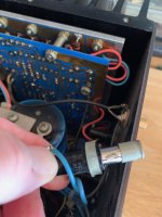
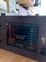
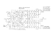
Good morning I recently picked up a threshold 400 an amplifier. The rail fuse holder has broken and I'm wondering if anybody has a part number? Hopefully it's just something as simple as it grounded against the chassis and popped the fuse, but who knows? I am equipped with an oscilloscope, signal generator, Variac, DVM and my son is an electrical engineering major so it would be great to see if we can get this thing going!! Thanks.
Attachments
just take measurements of fuse case and search for appropriate size on Digi or Mou
holder is a holder, if made properly
holder is a holder, if made properly
Google is your friend
https://www.digikey.ca/en/products/...GKFCkR4lzv0Pbv3q3tCA-9QHg1lQaM-RoCpDUQAvD_BwE
https://www.digikey.ca/en/products/...GKFCkR4lzv0Pbv3q3tCA-9QHg1lQaM-RoCpDUQAvD_BwE
Looks like there is a mfr part number on it, so look it up.
May still be available, or cross reference.
May still be available, or cross reference.
This appears to be the same as the original. When it shows up I will compare, but specs were right on with original per caliper. Note, slightly different link than KCIN earlier post.
https://www.digikey.com/en/products...3/1522963?s=N4IgTCBcDaIAxwMwEYB0yBsBWRIC6AvkA
https://www.digikey.com/en/products...3/1522963?s=N4IgTCBcDaIAxwMwEYB0yBsBWRIC6AvkA
So the fuse holder showed up and I soldered it in and it's a perfect fit. For $2.50 it was a bargain. The prior owner had the wrong line and rail fuses, so corrected all, then powered the unit up with a Variac. The left channel pegs at start up and produces 59 V DC at 120 V line in. The right channel is good with 27 mV at 120 V. Seems like a shorted output transistor??? but would like to know if you guys would think of anything else? I will look to change the electrolytic caps as well. Thank you, Doug.
This post seems right on point. https://www.diyaudio.com/community/...ing-rail-fuses-w-all-leds-illuminated.389596/
Odd, I just sent off a fuse clip (the gray piece) to someone else.
Must be some stellar alignment...
Must be some stellar alignment...
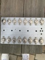
Morning! Can each output transistor be individually tested using an ohm meter without desoldering them from the circuit? The attached pictures indicate 4.5 ohms on one row and 2.5 or so on the other row there is one output transistor that tests noticeably lower .7 ohms, maybe that is the bad one causing the left channel to peak at turn on and throw the DC voltage? Any help you guys can contribute is appreciated. Thank you.
Attachments

Can each output transistor be individually tested
only if you lift one end of corresponding emiter resistor

Thank you guys for the replies. 50% less desoldering is a help. The resistors at the back of the output mounting board all tested at 1.2 or 1.3 ohms, with the exception of one of the orange banded ones which tested at 3.2 ohms.
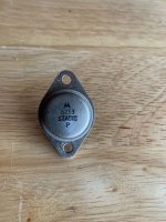
Evening DIY group. So the work continues, as the large can capacitors were replaced, and cleaned up the unit hoping to one day get it operational. A picture of the 1 output transistor which tested low at.7 ohms is attached. All 26 resistors tested same at roughly 1.5 ohms and none were split or burned. Lastly, when looking at the PCB, 2 of the resistors??? are partially burned, and need to be replaced, yet I could use help on part numbers, if someone can assist?? Thanks.
Attachments

- Home
- Amplifiers
- Pass Labs
- Threshold 400A fuse holder needed