Hi Guys
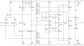
A very nicely drawn schematic! And small 'k' for kilo, too - great!
To adapt this to higher power requires adapting it to high-voltage output first. This just requires cascoding Q11,12 and using devices in the following stages that can handle the rail-to-ril output supplies. The base references forQ15,16 would have to be taken from these higher rails.
Then current gain is needed, so the output EF would have to become an EF driving mosfets, or at least an EF2 but more likely an EF3 or so.
A lot of high-power amps use a similar drive approach inasmuch as the input section drives a ground-referenced BJT pair connected in common-base, with the latter providing the level shifting to the VAS. The actual front-end inmany of these amps is an IC, which these days could just as easily have a folded-cascode input as a diff amp. The folded-cascode needs a clean supply rail to work against which is not a problem for the low-level circuitry as that can have regulated supplies. The emitters of Q15,16 should at least have decoupled supply nodes.
Have fun
Could be tricky. This opamp topology would need a major redesign to work on high supply rails and with the required current gain.
For example, the folded cascode frontend holds several advantages for general purpose opamp use (like very wide input common-mode range), but little more than one of them remains relevant in a high-powered amplifier - the output is not referenced to one of the supply rails. Apart from that, a conventional cascode input would be a better match - common-mode voltage swing tends to be relatively small, and there's a fair few more choices in input devices when high sustained voltage is not required.
Not to mention that a pure AB amplifier of 200-300 W / 8 ohms tends to become a bit of a power hog.
And small 'k' for kilo, too - great!
Hi,
Though I know its wrong I purposely always use "K" for kilo. It just makes
good sense, all multipliers are capital and all all dividers are lower case.
rgds, sreten.
Though I know its wrong I purposely always use "K" for kilo. It just makes
good sense, all multipliers are capital and all all dividers are lower case.
Good point, I wonder why the small k has been the standard?
Hi Guys
sgrossklass: you seem to have missed the ground right in the middle of the circuit. This separates the front-end from the VAS and output making it completely unnecesary to modify the front-end (left of that ground).
streten: Conventions exist to make communication easier. You would subvert the entire SI protocol?
K - Kelvin degrees, same as Centigrade or Celsius in size but the Kelvin scale starts at absolute zero as zero.
m - milli, one-thousandth
M - mega, one million
u - for micro since there is no mu key in ASCII
In Bob's book there are a couple of graphs where MHz is listed as mhz. Definitely an oversight as he is good about the conventions in the text.
Schematics get a bit sloppy when people use the spice conventions of "non-convention" (aka ASCII convenience), where lower-case and upper-case M or m mean milli, and if you really want "M" you have to type "meg".
The convention extends to the use of decimal points in values. It is easy in copying (fax, photo, etc) to lose a dot and a 01u cap could be 0.01u or 0.1u - an order of magnitude difference. This is where using the other prefixes is handy, as is using the prefix as the decimal holder. So 4.7k can be 4k7; 0.01uF becomes 10nF.
Now we should look at turning Veysel's u-amp into a M-amp.
Have fun
That is a Samuel Groner's circuit published in Linear Audio, Volume 2, page #106.
The general concept is very detailed in the article :
http://linearaudio.net/article-detail/2106
I think Samuel is currently using this circuit for the active stages of a sine generator having the highest performances.
The general concept is very detailed in the article :
http://linearaudio.net/article-detail/2106
I think Samuel is currently using this circuit for the active stages of a sine generator having the highest performances.
Last edited:
Hi Guys
The circuit is pretty generic considering the new generations of opamps that have come out in the last five years or so. It can easily be made into a power amp as post-2 describes. It can easily be used as a line amp or any small-signal function. I'm sure you will see it with lots of people's name on it.
Have fun
streten: Conventions exist to make communication easier.
You would subvert the entire SI protocol?
Hi,
No just part of it, its nonsense. You would write $2K, not $2k.
rgds, sreten.
Hi Guys
Streten: I DO write it the latter way because that is correct. You only see $2K because that is the ignorance of journalists trying to make a catchy headline.
What is worse in some ways is the medical community. They use "mcg" for microgram, instead of "ug" or a real mu there. I would think using some Greek letters in medicine would not be so out of hand considering they use so much Latin... hehe
Have fun
The circuit is pretty generic
Having two stages in a folded cascode configuration is a premiere to me.
One of the ideas is to avoid the usual falling of supply rejection due to Cdom (C3 here) in the two-stages standard configuration.
Hi Guys
forr, you can move the compensation cap to pretty much the smae place in a typical amp front end. Rather than returning Cdom to the base of the VAS, it can be taken to the feedback node. Cordell does this in his famous (and favourite) front-end, but then has to add further compensation across the diff-amp collectors.
The advantge of tying Cdom to the feedback node rather than to the VAS base is that PSRR can be improved as both ends of the cap are ground-referenced. Compensation and slew-rate are no longer tied together either.
Have fun
Hi Guys
forr, you can move the compensation cap to pretty much the smae place in a typical amp front end. Rather than returning Cdom to the base of the VAS, it can be taken to the feedback node. Cordell does this in his famous (and favourite) front-end, but then has to add further compensation across the diff-amp collectors.
Cdom connected to the feedback node was a scheme, lately called input inclusive, used Linsley-Hood in all his power amp designs.
It seems the conventionnal Cdom scheme allows a lower harmonic distortion.
In his article, Groner explains why his circuit has better linearity than the standard approach. It also has, aesthetically speaking, the appeal of a push-pull VAS without needing a complementary input. But it certainly requires a careful implementation.
Hi Guys
"It seems the conventionnal Cdom scheme allows a lower harmonic distortion"
That cannot be said as a blanket statement. However, Miller compensation is probably the easiest to work with to achieve stable operation and good performance very quickly, which is why all of the early opamps followed this architecture. The examples shown by Self are fairly good as "simplest forms" of the basic Miller-comp concept and provide good enough performance for the economically minded. Others have taken that form further with stellar results.
The alternate compensation scheme provide as good performance for those willing to work on it. Cordell's mosfet amp uses input-inclusive compensation achieving c3ppm THD and 300V/us slew rate in 1984, and there are better examples today in the ppb (Self got to 3ppm two decades later). The latest generation opamps use a variety of compensation schemes as more research demonstrates them to be of benefit.
Have fun
The alternate compensation scheme provide as good performance for those willing to work on it. Cordell's mosfet amp uses input-inclusive compensation achieving c3ppm THD and 300V/us slew rate in 1984, and there are better examples today in the ppb (Self got to 3ppm two decades later). The latest generation opamps use a variety of compensation schemes as more research demonstrates them to be of benefit.
The main source of distortion of a power amp is the output stage.
The main reason that 1984 Cordell's Mosfet amp had a very low distortion relies in its output stage which uses an Error Correction scheme inspired by the Hawksford's technique described in the JAES preprint #1974, February 1980.
Douglas Self published his first (as far as I know) complete blameless circuit of a power amp at the beginning of 1994, one decade later. Its circuit is simple and PCBs were soon available. Mine are working fine since.
Hi Guys
forr: The Self amps from the 90s did not come anywhere close to 3ppm, but his units of 2014 do using modern devices (t least for what he published - he makes coy remarks about "got a better idea but can't divulge it here"..) The basic design is timeless, age-old, tired, still has potential - take your pick - it is stable and is the ubiquitous circuit of most hifi amps ever built. Not his invention just his favourite and as an engineer who wants to make money for himself and for his clients, it is the model worth sticking with as it has fewer components than most things that work better.
The Cordell 1984 amp could have achieved the same performance without error correction, instead using other techniques known at the time. As with any other design, Bob made choices that appealed to his aesthetics. The front-end of that amp is fantastic. I've used it combined with BJT output stages and it easily achieves ppb THD. In his own words Bob stated that using BJTs would provide better raw performance than using mosfets, just as Hitachi admits in their mosfet amp paper.
For example, nested feedback has been known and used in audio amps since tube days. Were one intent on sticking with mosfets while using Bob's front-end circuit, the mosfets could be enclosed within a local loop of circuitry that would achieve the same goal as the EC but without the fiddly adjustments. Self makes contradictory statements about nested feedback, at one point it is highly beneficial and at another not worth the effort, and really it simply does not fit his aesthetic.
Have fun
forr: The Self amps from the 90s did not come anywhere close to 3ppm, but his units of 2014 do using modern devices (t least for what he published - he makes coy remarks about "got a better idea but can't divulge it here"..) The basic design is timeless, age-old, tired, still has potential - take your pick - it is stable and is the ubiquitous circuit of most hifi amps ever built. Not his invention just his favourite and as an engineer who wants to make money for himself and for his clients, it is the model worth sticking with as it has fewer components than most things that work better.
Self's amp is an optimised version of a generic design at the cost of nearly nothing.
What was new with it was the the extreme attention paid to details which were mostly overlooked up to this time.
The whole audio amp community has benefited a lot from Self's deep investigations in numerous areas of amplification.
I have been inspired by the load of the input stage used by Cordell but in an enhanced version proposed by Groner, Figure 56 ofThe Cordell 1984 amp could have achieved the same performance without error correction, instead using other techniques known at the time. As with any other design, Bob made choices that appealed to his aesthetics. The front-end of that amp is fantastic. I've used it combined with BJT output stages and it easily achieves ppb THD. In his own words Bob stated that using BJTs would provide better raw performance than using mosfets, just as Hitachi admits in their mosfet amp paper.
http://www.sg-acoustics.ch/analogue_audio/power_amplifiers/pdf/audio_power_amp_design_comments.pdf
to build a power amp.
There, the frequency compensation is has two caps but it is more conventionnal than the one used in Cordell's circuits.
It seems that a concern of high stability and absolute reliability is the main reason why Self did not finally adopt nested feedback schemes.For example, nested feedback has been known and used in audio amps since tube days. Were one intent on sticking with mosfets while using Bob's front-end circuit, the mosfets could be enclosed within a local loop of circuitry that would achieve the same goal as the EC but without the fiddly adjustments. Self makes contradictory statements about nested feedback, at one point it is highly beneficial and at another not worth the effort, and really it simply does not fit his aesthetic.
Hi Guys
forr: Yes, Doug has made the understanding of the distortion mechanisms in common amplifiers more visible and understandable to many people. He has also made statements about alternate topologies that are simply wrong, not because he can't do the math but rather because he has an aesthetic and an agenda that he has to serve. We all do this. He has invested himself fully in the Lin-Thompson circuit for its economy - a wide and deep English trait.
There are other circuits that work so much better as you have linked to. Self's work is great but you have to put it in perspective with the weight that it deserves and no more.
Have fun
There are other circuits that work so much better as you have linked to.
The circuit proposed in the first post could be one of them.
It is the subject of this thread.
I look forward feedback from those who have built it.
- Status
- Not open for further replies.
- Home
- Amplifiers
- Solid State
- This concept , design high power amplifier