Hi everyone,
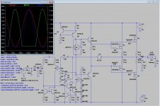
I've designed and simulated those three amplifiers, because as I said in previous posts I want to make a MOSFET amplifier, with my BUZ900P/905P that I've bought, I've this two designs, that are simple and they all use TMC for lower THD characteristics, I know that this characteristics (mainly THD20 should be lower), but the gate stopper resistors are killing the speed of the mosfet (I use them to prevent the appearing of Colpitts or Hartley unwanted oscillators), I've heared about the Zobels between gate and drain but this things can change the phase margins of the amp (and introduce some lag), and I've two output pairs of devices. Well, but the main purpose of this post is that if anyone of that topologies will work fine in the real world, and what's your oppinion.
I still need to incorporate a overload protection circuit (I'm think about using one of the circuits in Michael Kiwanuka's paper), another concern is thermal shutdown and DC offset protection (for those last two I'm thinking about using two relays to disconnect the mains, when the faulty condition is detected, but I don't know if it's a good idea), about relays I don't know much can anyone help me here?
Another questions are the parasitic oscillations (I'm concerned about the circuit Amp7_tmc.asc because of the Locanthi T circuit) and how to avoid them.
About this TMC schemes are a good idea or a bad idea, I should use another form of compensation?
I'm think about using regulation in the TCS/TIS (IPS/VAS) stages, I should use some sort of regulator or a resistor and two capacitors are sufficient?
Another problem I've never made a PCB for this kind of amp, what do you recommend?
What do you recommend for the heatsink, the amplifier will have two channels, what transistors should stay on the main heatsink(s), and the others? They need other heatsinks?
For 200 Wrms into 4 ohm and +/- 50V mains, what is the recommended heatsink(s) thermal resistance?
What thermal mass do you recommend?
PS: I'm trying to build this amp for almost 1 year, and I want to move on with this project and start to buy more stuff.
Best regards,
Daniel Almeida
Attachments
Last edited:
Thank you for your help ostripper 😉
Do you think I should use only one predriver?
This will waste less power, that's a fact and the amp will have a little less dissipation and less complexity in the PCB layout.
The characteristics are maintained?
As about oscillations it can work in real life?
As about Amp0_2 it's a bad idea?
Sorry for making all those questions.
Best regards,
Daniel
Thank you for your help ostripper 😉
Do you think I should use only one predriver?
This will waste less power, that's a fact and the amp will have a little less dissipation and less complexity in the PCB layout.
The characteristics are maintained?
As about oscillations it can work in real life?
As about Amp0_2 it's a bad idea?
Sorry for making all those questions.
Best regards,
Daniel
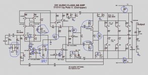
This amp is almost the same as the "honey badger". Look at it's schema for ideas.
Tips -
1. - replace Q8 , Q15-17 with MJE340/350. For really high performance , Q8,17 with 2sa1381/2sc3503 and Q15/16 with 2sa1837/2sc4793.
MJE243/253 has insufficient a Vce (100V).
2. Q6 goes to the main HS (Vbe) should be MJE340/2sc3503.
3. Q15/16 (drivers) can be on small PCB heatsinks. With a MOSFET OPS ,
you are only driving the gate capacitance of the outputs.
Otherwise.. look to the "DIYA class a/b amp" (badger) to use the improved reference for the current sources and
the CRC filters for the IPS/VAS. You could even use a cascode with a zener reference in the IPS to allow for a greater
selection of devices (low Vce-low noise) in the LTP/current mirror.
Amp 0_2 =


OS
Hello ostripper and thank you for your great help 😉
Unfortunatelly 2SC3503 and 2SA1381 are discontinued devices, it's a shame because they are very fast CRT video drivers.
What I can use instead?
Do you have any idea?
Do you have any idea of the low vce- low noise devices that I should use?
Do you have the models for MJE340/350 and 2sa1837/2sc4793?
PS:
Amp0_2 is bad because of the lower slew rate, right?
The Honey Badger seems a very good amp, I liked the circuit design very much, but I've few doubts in some components that I've signaled in blue, I want to know the reason for use them and if you think I should use them.
Can you explain me?
Did you designed the Honey Badger?
It seems just great. 😀
Best regards,
Daniel Almeida
Attachments
Last edited:
Fairchild make KSA1381/KSC3503, copies of them.
Sanyo used to make good transistors for the job too - since Onsemi bought them, they seem to have disappeared... 2SA1507/2SC3902 looks like they have potential
Sanyo used to make good transistors for the job too - since Onsemi bought them, they seem to have disappeared... 2SA1507/2SC3902 looks like they have potential
Hi there,
Thanks jaycee 😉
2SA1507/2SC3902 pair seems to be a good replacement, indeed. 🙂
Where I can get the models?
Could someone answer to the question I've made in my previous post, I'm trying to understand the purpose of some components in the Honey Badger amplifier to see if I should use them in my design as ostripper suggested.
Best regards,
Daniel
Hi everyone,
I've made a few changes, to make my design more similar to the Honey Badger but in a version with lower power and output MOSFETs, but when I changed my design, the THD20 characteristics at 8 ohm raised from 0.008% to 0.02% and the THD1 values from 0.00004% to 0.008%!!! I don't know what happened, can anyone help me here?
My desing is Amp7_tmc.asc, the design that I've made to supposedly improve performance is Amp7_tmc_hb.asc
Best regards,
Daniel
Attachments
Hi everyone,
Seems that almost all that distortion was caused by the input Zeners, I don't know exactly why, there's also another problem, the loading on the VAS is assymetrical because MJE15032 (530 uA) draws more base current than MJE15033 (330 uA), so I replaced this pair for a MJE243/MJE253 pair and now base current is almost exactly (340uA) per device.
Now THD20 is 0.02% for 4 ohm and 0.01% for 8 ohm.
THD1 is 0.00006% for 4 ohm load and 0.00005% for 8 ohm load.
Those are maximum values at full power, not typical values.
I'm wondering if I can lower THD20 a bit, can anyone help me?
Another problem, I really wanted to use the Zeners on the input and on the output to protect the input and output devices, but the Zeners causes great distortion when at the input, and the simulation cannot run if the Zener are used to limit Vgate, the problems could be from the models I'm using?
Best regards,
Daniel
Attachments
Last edited:
- Status
- Not open for further replies.
- Home
- Amplifiers
- Solid State
- This amps can survive in the real world?