Here’s a bit about the popular XY TDA2030A 2.1 DIY board and my PC stereo project.
This project started with a simple objective. I wanted a PC sound system for playing games and listening to digital music sources, mainly .mp3 but a growing amount of .flac. A big element of the design objective is that I really didn’t want a sub on the floor. I also wanted to spend nothing – that proved a bit too ambitious. So, best possible sound for least possible money ignoring labour.
I began by buying a pair of speakers on e-bay for a whole 99 pence. When I collected them I started to wonder if I had been robbed. The thing that caught my eye with these Aiwa speakers wasn’t the wood effect super cheap vinyl finish or the mock aluminium plastic fascia but the fact that they were 3 way with independently wired internal bass units. This gives the whole unit a pretty small footprint for quite a large speaker area. Judging by the component quality I expected these to sound pretty bad. Maybe as bad as 99 pence worth of junk.

I’ll come back to the speaker tart-up later.
This then led me to consider 2.1 amps and finally the XY board. I paid $7 including postage for the kit. The kit showed up with no parts list and no schematic and I wound up getting e-bay to get the seller to send me some instructions so I could figure out which resistors went where. I should have been cross but this was a $7 hobby project.
The circuit is pretty darn good but the board suffers from tiny pads. This isn’t a problem for most of the components but the rectifier, cable connectors and pots all need bigger solder areas.
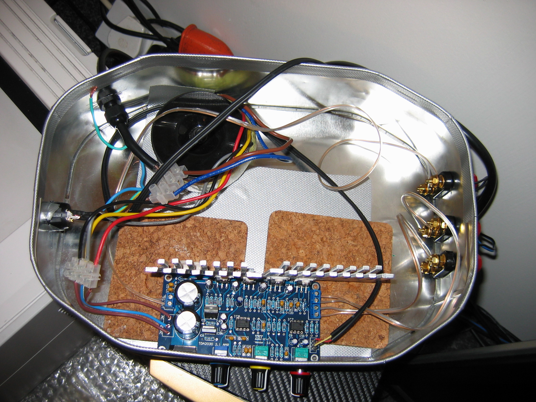
I powered the board with a reused 50VA 12 volt toroidal transformer. On board there is bridge rectifier that looks pretty manly and a couple of no special name 6800uF 25V caps. After rectification I measure about 18.3 volts DC.
The board has positive and negative 12 volt regulators – from memory I think these 78/79-12 regulators are good for about an amp and a half.
Two NE5532 op amps sort out the volumes.
There are 4 TDA2030A amps. Two for the left and right plus two bridged for the subwoofer. I have no idea what the filter for the sub is set to – 300 Hz?
The heat sinks are scavenged and are not satisfactory in several ways but they work well enough in this proof of concept biscuit tin.
This leads me to the only real problems that I have had with this build. The enclosure and the heat sink. If you build one of these you need to consider these two issues up front. I’ll be changing the heat sinks on mine but I think I’ll also be using mechanical ventilation – something I really wanted to avoid.
Back to the speakers. I threw away the cloth covers and recovered the speaker body with carbon fibre effect vinyl. I spray under coated all the visible plastic with Poundland white undercoat and the bass ports gloss black. Little bit of work with wet & dry paper. So £2 on paint. Then I totally broke the bank on a can of Rustoleum gold. £8. Just like that. I was throwing money about like the European Commission that day.
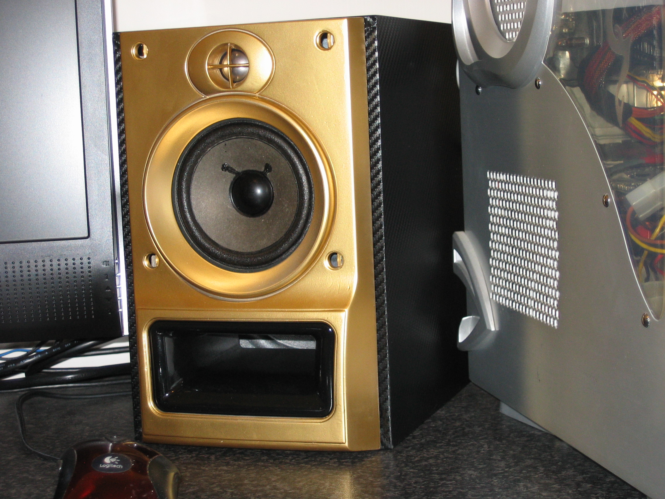
I found out later that gold looks better on a matt black undercoat. C’est la vie.
Anyhow what does it sound like?
Really good is the answer. The internal subwoofers are wired in series to the amp sub out.
The sound is really rich, defined and precise - the whole thing sounds a thousand times better than it ought to. I’m not just saying that by the way. Getting the base up from the floor was a practical concern but I think it’s way better sound wise.
Now I have a question for you. Is it feasible to use ordinary bi-wire able speakers with the base inputs connected in series to the BTL amps with other connectors to the left and right channels?
This project started with a simple objective. I wanted a PC sound system for playing games and listening to digital music sources, mainly .mp3 but a growing amount of .flac. A big element of the design objective is that I really didn’t want a sub on the floor. I also wanted to spend nothing – that proved a bit too ambitious. So, best possible sound for least possible money ignoring labour.
I began by buying a pair of speakers on e-bay for a whole 99 pence. When I collected them I started to wonder if I had been robbed. The thing that caught my eye with these Aiwa speakers wasn’t the wood effect super cheap vinyl finish or the mock aluminium plastic fascia but the fact that they were 3 way with independently wired internal bass units. This gives the whole unit a pretty small footprint for quite a large speaker area. Judging by the component quality I expected these to sound pretty bad. Maybe as bad as 99 pence worth of junk.
I’ll come back to the speaker tart-up later.
This then led me to consider 2.1 amps and finally the XY board. I paid $7 including postage for the kit. The kit showed up with no parts list and no schematic and I wound up getting e-bay to get the seller to send me some instructions so I could figure out which resistors went where. I should have been cross but this was a $7 hobby project.
The circuit is pretty darn good but the board suffers from tiny pads. This isn’t a problem for most of the components but the rectifier, cable connectors and pots all need bigger solder areas.
I powered the board with a reused 50VA 12 volt toroidal transformer. On board there is bridge rectifier that looks pretty manly and a couple of no special name 6800uF 25V caps. After rectification I measure about 18.3 volts DC.
The board has positive and negative 12 volt regulators – from memory I think these 78/79-12 regulators are good for about an amp and a half.
Two NE5532 op amps sort out the volumes.
There are 4 TDA2030A amps. Two for the left and right plus two bridged for the subwoofer. I have no idea what the filter for the sub is set to – 300 Hz?
The heat sinks are scavenged and are not satisfactory in several ways but they work well enough in this proof of concept biscuit tin.
This leads me to the only real problems that I have had with this build. The enclosure and the heat sink. If you build one of these you need to consider these two issues up front. I’ll be changing the heat sinks on mine but I think I’ll also be using mechanical ventilation – something I really wanted to avoid.
Back to the speakers. I threw away the cloth covers and recovered the speaker body with carbon fibre effect vinyl. I spray under coated all the visible plastic with Poundland white undercoat and the bass ports gloss black. Little bit of work with wet & dry paper. So £2 on paint. Then I totally broke the bank on a can of Rustoleum gold. £8. Just like that. I was throwing money about like the European Commission that day.
I found out later that gold looks better on a matt black undercoat. C’est la vie.
Anyhow what does it sound like?
Really good is the answer. The internal subwoofers are wired in series to the amp sub out.
The sound is really rich, defined and precise - the whole thing sounds a thousand times better than it ought to. I’m not just saying that by the way. Getting the base up from the floor was a practical concern but I think it’s way better sound wise.
Now I have a question for you. Is it feasible to use ordinary bi-wire able speakers with the base inputs connected in series to the BTL amps with other connectors to the left and right channels?
With an ordinary bi-wire able speaker the active filter of the amp will conflict with the passive filter of the speaker. It works for you now because there is no passive filter for the sub-bass drivers.
Thanks. That's what I thought.With an ordinary bi-wire able speaker the active filter of the amp will conflict with the passive filter of the speaker. It works for you now because there is no passive filter for the sub-bass drivers.
These rubbish speakers work very well in the 2.1 configuration. I've never seen any other speakers made this way.
Did you correctly connect the sub-bass drivers in phase?
By accident or design. I think they are great.
By accident or design. I think they are great.
Each speaker cabinet has two pairs of wires that just appear out of the woodwork. I have connected the internal bass speakers in series to the sub output terminals on the amp which are driven by 2 TDA2030As in bridged configuration. I just assumed this was the way to do it such that each individual amp still 'sees' a nominal 8 ohm load (they purport to be 8 ohms both ways).
I intended to do that when I bought them but I didn't expect it to sound too good. Maybe I just got lucky all round. I used to have an Altec Lansing 2.1 PC stereo which had a big floor standing sub - this one sounds just as good.
An odd thing that I've noticed is that it doesn't seem to be running so hot as when I first made it. Duh?
Running at three quarters of full wick I can grip the heat sinks without the smell of burnt flesh. Crikey. I hope I'm not losing my sense of smell.
Thanks for your reply and comment.
All the best
Graham
If you get the polarity of the drivers wrong, they will be out of phase, you will get a cancellation of sound.
Normally you can test the drivers polarity with a 1.5 V battery (without amp connected). Both drivers will make the same movement, a bit difficult if you can't see the drivers.
For the sub-bass driver you should be able to hear if they are out of phase.
connections:
amp L out - driverL plus / driverL min - amp L return
amp R out - driverR plus / driverR min - amp R return
amp sub out - sub driver1 plus / sub driver1 min - sub driver2 plus / sub driver2 min - amp sub return
Last edited:
- Status
- Not open for further replies.
- Home
- Amplifiers
- Chip Amps
- The XY TDA2030A DIY Board and Aiwa Speakers