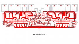
here is my latest lay out for an amplifier i make that i call the QLA amplifier (name to be explained in the feature )
demo board and testings are allready done but my previous lay out was way too compact ( very very compact ) that actually had no mistake but the temperature collected in such a small area was a mistake
also previous lay out was only made for 21193 4 while this one may also use biger like 1943-5200
so i thought that is better to have 10 transistors in a length of 30 cm than 15 than the previous f@cking compact pcb was ( costly mistakes 😡)
at this point i will only post the lay out ..it is supposed to be a pro amp and happily working for 350 w @ 8R
further testings schematics and more from this after the pcb is done in the factory
kind regards sakis
Attachments
Last edited:
Hi Sakis - neat looking pattern!
Without calculation, just knowing similar power and 4 each MJL 21193/4 or
2SC 5200 etc. you should get a nice long life wth 5 each transistors producing 350 W into 8 Ohm.
All the same, if not bolting transistors staight to the heatsink, a heavy bracket
(say > 8 mm) is good to avoid hotspots.
regards
Member
Joined 2009
Paid Member
well ...in all these years i do PA and construct amplifiers if the amplifier failed there was no fuse enough to prevent explosion ...
i also dont really belive in DC protection ... i am more like a crow bar person if the amplifier has DC in the out cause it failed what diference does it make if it blows one tranistor or all ??? not much since your amp doesnt work anyway and the cost of the gig you loose is by far more than the cost of a few tranistor
then again i have pcb that has rail fuses but for this design is not really effective cause if for accident you loose one fuse then you loose the all amp
you actually need to fuse the amp partially at the output stage ,,,, didnt do that ...will see how its going to work
i have released to work my first ldr limmited amplifier and will se also how it goes as we speak there is kids pushing it death ( at least it has crow bar if something goes wrong )
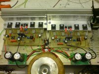
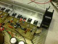
the qla amplifier comes to life ....one step at time this particular version is something kinda small to listen too ... only 52+52 rails only 2pairs of outputs pair board
this is constructed to listen to cause it measures quiet ok but music has to come out of it after all ...
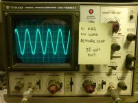
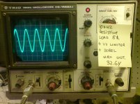
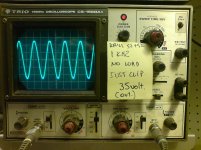
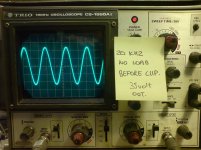
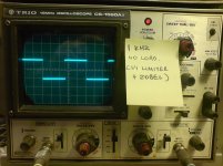
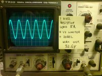
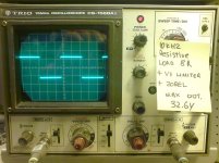
yet again this version ( even the small one ) includes complete Vi limmiter so ....here is some pictures instead of a 1000 words
the complete box is going to be finalized inside a sory excuse for an amplifier that used to be called milbank .... world famous 100 V amplifier company (world famous in uk 😀😀😀 ) ...i dont realy expect to look nice when finished ... but as i said this just a demo version hell not even the pcb belongs to the amplifier its a mod from another amplifier but thats ok ... new pcb is on the way
VI limmiter is in a piggy board located down under
regards sakis
this is constructed to listen to cause it measures quiet ok but music has to come out of it after all ...
yet again this version ( even the small one ) includes complete Vi limmiter so ....here is some pictures instead of a 1000 words
the complete box is going to be finalized inside a sory excuse for an amplifier that used to be called milbank .... world famous 100 V amplifier company (world famous in uk 😀😀😀 ) ...i dont realy expect to look nice when finished ... but as i said this just a demo version hell not even the pcb belongs to the amplifier its a mod from another amplifier but thats ok ... new pcb is on the way
VI limmiter is in a piggy board located down under
regards sakis
Attachments
-
 demo version front.JPG169.8 KB · Views: 155
 -
 demo version left.JPG169.5 KB · Views: 154
 -
 demo version right.JPG160.2 KB · Views: 142
 -
 measure 3.JPG128.8 KB · Views: 52
 -
 measure 2.JPG94.2 KB · Views: 54
 -
 measure 1.JPG131.6 KB · Views: 140
 -
 measure 4.JPG137.7 KB · Views: 49
 -
 measure 5.JPG147 KB · Views: 46
 -
 measure 6.JPG129.3 KB · Views: 44
 -
 measure 7.JPG126.2 KB · Views: 54
The more copper the better, it costs nothing to have more copper, otherwise it just gets etched away.
Ground planes are good too.
Ground planes are good too.
hei nigel ... hm mmmm ok yes i will agree with the copper thingy but as is said this is a demo version
the original pcb that is going to be used is the one seen on the top ...and since i dont use solder mask some of the needed traces will be feed up with extra soldering to achive thickness
as about ground planes its something ive never done and never will ...i just dont like them ...thanks though
the original pcb that is going to be used is the one seen on the top ...and since i dont use solder mask some of the needed traces will be feed up with extra soldering to achive thickness
as about ground planes its something ive never done and never will ...i just dont like them ...thanks though
Last edited:
as about ground planes its something ive never done and never will ...i just dont like them ...thanks though
A ground plane connected to ground or zero volts will reduce the impedance of the ground line and so help with possible hum problems.
well yes it might but then again you need to think if you need your ground plane to exist there as "a protection method " IE acting as a shield on your pcb... and then be returned to O volt ...so the reducing of impedance doesnt apply ...
if you use the ground plane as a ground supply to where ever is needed you simply destroy with that the start ground concept ...
so what exactly is the beneffit of a ground plane ???? i think in AF amplifiers is not usefull ...it could be in digital or RF devices ...
only option one could be of some use ... but inductunce and capacitance might created from a bad made GP could make things worst
just a few thoughts
well yes it might but then again you need to think if you need your ground plane to exist there as "a protection method " IE acting as a shield on your pcb... and then be returned to O volt ...so the reducing of impedance doesnt apply ...
if you use the ground plane as a ground supply to where ever is needed you simply destroy with that the start ground concept ...
so what exactly is the beneffit of a ground plane ???? i think in AF amplifiers is not usefull ...it could be in digital or RF devices ...
only option one could be of some use ... but inductunce and capacitance might created from a bad made GP could make things worst
just a few thoughts
I was thinking more of using the empty space on the pcb as a zero volt plane. Anything that reduces the zero volt line impedance is good and reduces possible positive feedback in the amp to the input stage. After all there are some pretty hefty currents floating around a power amp.
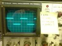
beyond the above amplifier is up and runing ...listening impressions are very detailed ( even with very very low bias ) bass is punchy and plenty midle is detailed and treble is very rich ...
macine sounds relativelly powerfull ( eventhough VI limited ) and taking in mind that this version produces around 120 W i think that everything seems to work fine ....
will listen more ...push more and see how it goes
other than that ...waiting for the big board with 10 outputs to see how it will go ( rails 70-80 volts .... will see )
- Status
- Not open for further replies.
- Home
- Amplifiers
- Solid State
- The qla amplifier