There's a bit of consternation about the future of Class AB amplifiers because the transistors may get scarce, especially with the move to SMT and the ongoing semiconductor shortage.
https://www.diyaudio.com/forums/parts/373697-class-ab-endangered-8.html
I decided to take a shot at seeing how good of a power amplifier can be made using just two sets of transistor parts: 2N5551/2N5401 and TIP41C/TIP42C. In particular, 2N5551/2N5401 and TIP41C/TIP42C both have generic versions from Chinese manufacturers that seem to work pretty well, for example:
ST(Semtech)|ST(Semtech) 2N5551|Bipolar Transistors - BJT|LCSC
ST(Semtech)|ST(Semtech) 2N5401|Bipolar Transistors - BJT|LCSC
SPTECH|SPTECH TIP41C|Bipolar Transistors - BJT|LCSC
Changjiang Electronics Tech (CJ)|Changjiang Electronics Tech (CJ) TIP42C|Bipolar Transistors - BJT|LCSC
Because of the large number of versions, it seems these parts are good candidates to not be discontinued in the near future.
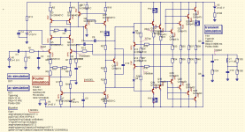
The result is: pretty good. The simulations seem to indicate that 180 W can be delivered to a 4 ohm load with THD 0.01% to 0.02% at 20 kHz. The design uses an output triple darlington, single ended VAS and cascode input, and is protected against overvoltage input and has a V-I limiter that cuts current when the load resistance is below 2 ohms. The power rails are up to 45 V. There is 108 dB of open loop gain with a gain margin of 15 dB and a phase margin of over 90 degrees.
https://github.com/profdc9/PowerAmpAudio/tree/master/PowerampSimpleParts
The current design uses conventional Miller compensation but there are inclusions on the board for TPC and OITPC compensation components.
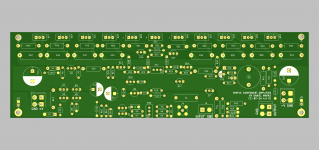
I laid out a PCB for it and it seems to be reasonably compact. There are four TIP41C/TIP42C on each rail.
This could be a pretty good budget amp I think.
https://www.diyaudio.com/forums/parts/373697-class-ab-endangered-8.html
I decided to take a shot at seeing how good of a power amplifier can be made using just two sets of transistor parts: 2N5551/2N5401 and TIP41C/TIP42C. In particular, 2N5551/2N5401 and TIP41C/TIP42C both have generic versions from Chinese manufacturers that seem to work pretty well, for example:
ST(Semtech)|ST(Semtech) 2N5551|Bipolar Transistors - BJT|LCSC
ST(Semtech)|ST(Semtech) 2N5401|Bipolar Transistors - BJT|LCSC
SPTECH|SPTECH TIP41C|Bipolar Transistors - BJT|LCSC
Changjiang Electronics Tech (CJ)|Changjiang Electronics Tech (CJ) TIP42C|Bipolar Transistors - BJT|LCSC
Because of the large number of versions, it seems these parts are good candidates to not be discontinued in the near future.
The result is: pretty good. The simulations seem to indicate that 180 W can be delivered to a 4 ohm load with THD 0.01% to 0.02% at 20 kHz. The design uses an output triple darlington, single ended VAS and cascode input, and is protected against overvoltage input and has a V-I limiter that cuts current when the load resistance is below 2 ohms. The power rails are up to 45 V. There is 108 dB of open loop gain with a gain margin of 15 dB and a phase margin of over 90 degrees.
https://github.com/profdc9/PowerAmpAudio/tree/master/PowerampSimpleParts
The current design uses conventional Miller compensation but there are inclusions on the board for TPC and OITPC compensation components.
I laid out a PCB for it and it seems to be reasonably compact. There are four TIP41C/TIP42C on each rail.
This could be a pretty good budget amp I think.
Attachments
So is that inferring that perhaps the precious laterals may not have a solid future in this world?
I couldn't say. Based on the thread, Profusion says that they should remain available, so I don't have any reason to believe they won't be. Still, this was more of an exercise motivated by the possible reduction in availability of parts.
I do not see SMT as being not being useful to build projects with. However, having through-hole parts is nice for some to make simple projects. However, class AB dissipates power which often requires through-hole components that can be heatsink mounted. Class D, which is replacing class AB because of its power efficiency, uses MOSFETs that can be surface mounted and use the PCB as a heat sink because over the lower power dissipation. It is clear that class D amplifiers will continue to dominate, but if one wants a design easier to build and tinker with, a class AB with through-hole parts is going to be easier for the hobbyist. One of the whole points of DIY is to have something that can be a learning tool as well as useful project that one can assembled preferably from readily available materials, in my opinion.

To be honest the main thing that is hard to get now is devices suitable for VAS use. There are some good ones in SOT-223 format which is not impossible to hand solder. I dont expect power devices suitable for audio use will be going anywhere for a long time - even vertical mosfets made for switching can be used and some of them have excellent characteristics
To be honest the main thing that is hard to get now is devices suitable for VAS use. There are some good ones in SOT-223 format which is not impossible to hand solder. I dont expect power devices suitable for audio use will be going anywhere for a long time - even vertical mosfets made for switching can be used and some of them have excellent characteristics
In the design above, I used a 2N5551/2N5401 for the VAS. There is only 1.5 mA of current in the VAS. The output triple darlington is used so that not much current is required from the VAS. Perhaps such an approach could be used elsewhere.
In the design above, I used a 2N5551/2N5401 for the VAS. There is only 1.5 mA of current in the VAS. The output triple darlington is used so that not much current is required from the VAS. Perhaps such an approach could be used elsewhere.
Cascodes tend to work better, as the power device can then be fairly "slow". A little bit of headroom loss is the only penalty, and if you really want to get over that it's a simple matter to build a Cockroft type voltage multiplier to boost the rails for the LTP+VAS stage
However, there are devices.. for example Nexperia have BF620/BF621 which are pretty much the modern versions of BF469/470 in SOT-89 - not impossible to solder, and can be effectively heatsinked by a large copper area.
Another good candidate pair is Diodes Inc DZT5401/5551 which as the names suggest are 2N5401/2N5551 devices in a SOT-223 package, allowing for better power dissipation than TO-92 devices.
Another good candidate pair is Diodes Inc DZT5401/5551 which as the names suggest are 2N5401/2N5551 devices in a SOT-223 package, allowing for better power dissipation than TO-92 devices.
Nexperia and Infineon do or did also make BF722,723 which are larger SOT223 versions of the log obsolete BF469/70. These are higher rated but also much easier to solder a flag type heatsink to, if required.
That happened already, decades ago... Many transistors that people think have dissapeared are available as SMT with a new part number, and new transistors only appear as SMT (unless high power).especially with the move to SMT
That's a short term blip surely, not a trend, annoying though it is.and the ongoing semiconductor shortage.
I'd say the big ongoing trend is to class D for audio, and to digital for audio interconnect.
The trend of consolidation where fewer types are available will continue. Parts, especially ones used in class AB amps will keep going obsolete. Eventually, what will be left are a few premium (expensive) types, which may or may not be available where you live. I can get stuff from Mouser, but I live in Texas. If the only thing you can get thru customs is generics and fakes, that’s another story. And some people’s finances may NEVER recover from recent events. I’ve certainly been there - in those lean years it was build with generics, pulls, and Radio Shack parts, or you don’t build at all. Anyone here remember when Mouser didn’t sell a single transistor rated over 80 volts, Digikey didn’t even know what a power transistor was, And minimum orders of $250 or more, or commercial account requirements prevented you from using REAl distributors? I sure do. TIP42 were it. And you had to test the no-suffix version to screen the voltage yourself, too. And most of them WOULD take the full 100V, BTW.
One of the reasons I think Class AB retains some appeal is because it is reasonably simple, not that inefficient, and can be tinkered with readily, and is a good project for those trying to learn electronics.I'd say the big ongoing trend is to class D for audio, and to digital for audio interconnect.
Class D is typically implemented by monolithic ICs in consumer electronics, perhaps with external MOSFET switches to handle the power needed. Certainly one could homebrew their own Class D design from scratch, but reaching the audio quality of a commercial Class D amplifier is not a beginner project. There are few Class D designs that don't use a monolithic IC. I found one for example:
HiFi Class-D Discrete Power Amplifier - Electronic Circuit
I have no idea if this works but it was one of the few examples I could find that might be hackable.
Using SMT, class AB designs will probably survive a bit longer as long as discretes are needed. However, I am afraid audio electronics is going to become like digital electronics and computation: consumer electronics by and large has become too complex to understand or build yourself. When was the last time a person built a PC from scratch, creating a motherboard and such? One can still do that with a Z-80 processor, which while ancient, provides some insight into computer design. Hopefully DIY audio can have the same role for audio technology as a stepping stone into more complex projects.
To profdc: would you consider using TIP35/6 valid as a “doomsday amp” or would that be cheating? I have a 120-or-so watt per channel at 8 ohm class H in development using the bigger TIPs (quad 28 volt rails). It is kind of back burnered for the moment while I work on ones that are a lot bigger - but I have a starting schematic around *somewhere*. I’m pretty sure it was posted somewhere here a few years ago. I suppose it would be possible to use paralleled TIP41/2 there too. I’ve got a whole bunch of 20-0-20 5A toroids to build a batch of them some day. As well as plenty of TIPs.
I think TIP35C/36C are ok, but there are many more manufacturers of generic TIP41C/42C than generic 35C/36C and so 41C/42C makes a better "doomsday" part, and it is easier to get good performance with more paralleled TIP41C/42C than fewer TIP35C/36C. A quick simulation has suggested that the crossover distortion would be significantly greater with the 35C/36C, though that could be just because good SPICE models are not available for 35C/36C (there seems to be some issues here). The generic 41C/42C are quite a bit cheaper as well, even factoring in that you need more of them. The biggest pain with the 41C/42C is having to mount more of them to a heatsink.
Practical experience with them:To profdc: would you consider using TIP35/6 valid as a “doomsday amp” or would that be cheatingusing the bigger TIPs (quad 28 volt rails).
I make Guitar Amps commercially for 50 years now, TIP35/36 look impressive on paper, in practical use they are wimpy sissies 😱 , *explode* (literally) when used under live/stage conditions.
Not sure why, under test they meet voltage specs, *high* current specs ... but they die quickly, using same supplies and speaker loads humble 2N3055 fare FAR better.
I´m talking 2N3055 available between 1970 and 1990, afterwards these declined too .... but TIP35/36 NEVER were strong enough.
I´m currently (since 2004-2008) using TIP142/147 and they are very robust, trustier than 35/36, go figure.
I **guess** when they designed them for 100V and impressive (way back then) 25A they left out second breakdown capability which is a deal breaker when driving real world speaker loads.
Notice that even after being available for some 40 years (or more), "nobody" uses them. There must be a reason for that.
Gallien Krueger used parallel TIP33/34 in their 100W amplifiers (+/-45V rails, 4 ohm load) which are robust, while they *could* have used a single pair TIP35/36 yet they didn´t.
Traynor used them briefly, then upgraded to single pair MJ802/4502.
Maybe your quad rail amps have no problem, if each transistor sees low voltage on its own, SOAR decreases dramatically with voltage so if you keep it well under spec, you might have better chances.
Keep us updated. 🙂
PS: TIP41/42 are quite strong within their spec class.
My experience is that they hold up just fine on +/-28 volt supplies, even when driving heavy loads. Many old school car amps used them around that voltage and you know people bridge into 4 ohms to make 200 watts. The POR for the amp is to run a tracking type (not switching) class H, so the upper transistor would never see more than 32 volts or so even driving reactive loads. I could get away with only the single pair per rail, not needing emitter resistors to balance multiple uppers. The current gain of real TIP35s is enough to do this - it would take four TIP41’s to get there beta droop wise. And THAT’s a pain to mount on the heat sink. Not to mention the space of sixteen emitter resistors per channel. The target application of these is to drive multiple compression drivers or perhaps get pulled for light monitor duty so high frequency performance needs to be pretty good. Non switching class H with schottky commutating diodes will do it pretty clean.
I haven’t decided on a front end yet - whether to use a conventional diff pair, CFA, the usual op amp front end I use on the big stuff. All have their merits. The op amp is easy and requires nothing critical anywhere, and simplifies integrating all the “supervisory” functions that will be needed anyway. The diff pair is “doomsday ready” as long as I can find two matched input pairs (per amp). The CFA would have the best high frequency performance, but I’m going to want C3503/A1381 VAS and C1845/A992 inputs - which moves further away from the original concept of using generic parts. I could build a really good one later, using the “best of the best” and go with Sanken darlington outputs (they make a nice 25A 120V pair).
That’s the ONE reason I never went through with the “all 2N3055” 200 watt per channel build I was looking at several years back. Bridged, using stacked cascodes, single supply. A lot of 3055’s. It’s a LOT of machine shop work for what you get. I still have the PCB design, and may get it fabbed one day when I have time to do all that drilling. It was intended to be. “Doomsday amp”. Maybe Doomsday will be the time to do it.
I haven’t decided on a front end yet - whether to use a conventional diff pair, CFA, the usual op amp front end I use on the big stuff. All have their merits. The op amp is easy and requires nothing critical anywhere, and simplifies integrating all the “supervisory” functions that will be needed anyway. The diff pair is “doomsday ready” as long as I can find two matched input pairs (per amp). The CFA would have the best high frequency performance, but I’m going to want C3503/A1381 VAS and C1845/A992 inputs - which moves further away from the original concept of using generic parts. I could build a really good one later, using the “best of the best” and go with Sanken darlington outputs (they make a nice 25A 120V pair).
I The biggest pain with the 41C/42C is having to mount more of them to a heatsink.
That’s the ONE reason I never went through with the “all 2N3055” 200 watt per channel build I was looking at several years back. Bridged, using stacked cascodes, single supply. A lot of 3055’s. It’s a LOT of machine shop work for what you get. I still have the PCB design, and may get it fabbed one day when I have time to do all that drilling. It was intended to be. “Doomsday amp”. Maybe Doomsday will be the time to do it.
That’s the ONE reason I never went through with the “all 2N3055” 200 watt per channel build I was looking at several years back. Bridged, using stacked cascodes, single supply. A lot of 3055’s. It’s a LOT of machine shop work for what you get. I still have the PCB design, and may get it fabbed one day when I have time to do all that drilling. It was intended to be. “Doomsday amp”. Maybe Doomsday will be the time to do it.
If you are going to run it off of +/- 28V supplies, you can likely get away with fewer transistors than four per rail. I think four will be needed to go to +/- 45 V, but for +/- 28 V three is certainly sufficient and probably two is OK. Four transistors are also used to reach a low level of distortion by reducing output impedance, which I felt should be comfortably below 0.1%. On a more qualitative note, I think lower output impedance results in better control of the speakers which affects the sound that way for real life loads.
Mounting eleven devices equally spaced on a heatsink is not that difficult of a machining task. For my last amp where I mounted 11 devices to a heatsink, I was able to drill and hand tap the holes in about 2 hours. It's not stacked cascodes of paralleled transistors with bridged amplifiers so you need four times the output transistors.
Good idea. I had already thought about this due to the stock I have of BC5xx and TIP4x. Perhaps three pair TIP4xC could be considered similar to one 2SC5200/2SA1943 pair, in terms of power dissipation (to be confirmed) up to +-40V.
Last edited:
Good idea. I had already thought about this due to the stock I have of BC5xx and TIP4x. Perhaps three pair TIP4xC could be considered similar to one 2SC5200/2SA1943 pair, in terms of power dissipation (to be confirmed) up to +-40V.
I used Doug Self's circuit model of a two-way speaker, halving all of the impedances to make it a 4 ohm speaker rather than an 8 ohm speaker (a worst case).

I then simulated 25 Hz and 6000 Hz frequencies which are the worst frequencies for peak currents to find the instantaneous current and voltage through one of the transistors to see if SOA and power limits are exceeded.

At 25 Hz, the peak SOA excursion occurs at 20 Volts output at IC=1.75 A, which corresponds to VCE=25 V, and is a point within the DC SOA of the TIP41C (which means it could be tolerated indefinitely with sufficient heatsinking). This condition occurs during the cycle at an instantaneous power dissipation of about 40 W, and with an average power dissipation of about 15 W.

At 6000 Hz, the peak SOA excursion occurs at approximately 0 Volts output with IC=1.75 A, or VCE=40 V. This is slightly outside of the DC SOA but needs to be sustained only briefly during the 166 microsecond cycle. The peak power is 70 W but is sustained over only a small portion of the cycle.

Keep in mind this is a worst case of driving a 4 ohm reactive speaker load (with Self's model) with a full amplitude continuous sine wave. It is not likely to encounter this in practice.
I think this supports that the four TIP41C/42C should be able to reasonably sustain a speaker load up to perhaps 200 W.
- Home
- Amplifiers
- Solid State
- The doomsday amp