I am designing a small VT regulator using two compactron tubes (6FM7 and 6K11). I want to know the best method (Analog) to measure or almost estimate the output impedance of it. Please, discard the stupid idea of loading it until Vo reaches ½ its normal value because it will cause the destroy of it, and it says me the static resistance but not the dynamic resistance (Slope).
Simple: run it no-load and at full rated load. Measure sag, do math.
Complete: run it at all likely load currents and inject AC signal to the output. The output impedance will change with pass-tube current. The output impedance will be different at all frequencies.
Why does it even matter? A sufficiently large rail cap will give low-enough impedance over the audio band. Tube amplifiers (I assume what you want this for) rarely need extreme low DC impedance because they are not DC coupled.
No need to load it down to 50% of raw voltage which I agree is murderous, but you can load it down to 5% or 10% drop, in any case keep it within ratings so as not damaging anything, and do the Math.I am designing a small VT regulator using two compactron tubes (6FM7 and 6K11). I want to know the best method (Analog) to measure or almost estimate the output impedance of it. Please, discard the stupid idea of loading it until Vo reaches ½ its normal value because it will cause the destroy of it, and it says me the static resistance but not the dynamic resistance (Slope).
As of the slope: delta V/delta I .
Sorry my keyboard does not let me introduce symbols.
Of course, others may have another methods.
PD: if slope is not linear, then you gradually load it , measure resulting voltages and draw a graph.
Say your regulator is capable of 20mA out, then load it with 2 - 4 - ... 18 - 20 mA (and even once, for testing, continue to 26 or 28 mA) , you will have 10 or 12 points , your hand drawn curve will be quite accurate.
Last edited:
The loading method is almost useless for a variety of reasons: vector impedance, non-linearity, etc.
The standard method is that outlined by PRR, using a VNA as a source for stimulus + response measurement (with suitable port protections to deal with the HV, of course).
At a DIY level, a full-feature VNA, even from "cheap" asiatic vendors is probably not an option, thus your best bet is probably to duplicate a SNA using a generator and a microvoltmeter (both suitably protected, again), and it will work reasonably well if your supply has moderate performances.
If the impedance is really low, you will have difficulties extracting the real impedance from a background of noise and ripple.
It is possible to build a simple (and expendable) VNA mock-up jig, using as a stimulus a power MOSfet switch associated with series and // power resistors, to define the load current and the step size, and a simple synchronous rectifier to measure the (~vector) result.
Here is a simplified ouline of the test-jig:

Total BOM:
-1 squarewave generator (CD40106 oscillator or bench function generator)
-1 HV power MOSfet
-2 adjustable (or even fixed) power loads
-1 cheap dual opamp
-1 cheap analog switch (CD4053 is perfect)
-A few glue and protection passives
It will make µΩ-level impedances accessible for frequencies of ~0 to at least 10kHz using just a simple multimeter as display device.
The measurement will be made using a squarewave, not a sine, meaning there will be some minor inaccuracies, but most of them will be eliminated by the syn-rect + LPF processing.
The vector nature of the impedance could cause more severe inaccuracies, and if it is a problem, you could "explore" the phase, by varying the phaseshift between the generator and the sync-rect.
The standard method is that outlined by PRR, using a VNA as a source for stimulus + response measurement (with suitable port protections to deal with the HV, of course).
At a DIY level, a full-feature VNA, even from "cheap" asiatic vendors is probably not an option, thus your best bet is probably to duplicate a SNA using a generator and a microvoltmeter (both suitably protected, again), and it will work reasonably well if your supply has moderate performances.
If the impedance is really low, you will have difficulties extracting the real impedance from a background of noise and ripple.
It is possible to build a simple (and expendable) VNA mock-up jig, using as a stimulus a power MOSfet switch associated with series and // power resistors, to define the load current and the step size, and a simple synchronous rectifier to measure the (~vector) result.
Here is a simplified ouline of the test-jig:
Total BOM:
-1 squarewave generator (CD40106 oscillator or bench function generator)
-1 HV power MOSfet
-2 adjustable (or even fixed) power loads
-1 cheap dual opamp
-1 cheap analog switch (CD4053 is perfect)
-A few glue and protection passives
It will make µΩ-level impedances accessible for frequencies of ~0 to at least 10kHz using just a simple multimeter as display device.
The measurement will be made using a squarewave, not a sine, meaning there will be some minor inaccuracies, but most of them will be eliminated by the syn-rect + LPF processing.
The vector nature of the impedance could cause more severe inaccuracies, and if it is a problem, you could "explore" the phase, by varying the phaseshift between the generator and the sync-rect.
As of the slope: delta V/delta I .
Sorry my keyboard does not let me introduce symbols.
It's ΔV/ΔI, isn't it 😉?
Best regards!
Last edited:
By using an AP you can plot the DATA directly as the COMPUTE function is used. It sweeps Unloaded then Loaded and then displays the graph. Other analyzers may do the same. Using a Sound card and sending DATA to Excel and graphing is another way.
Duke
Duke
Thanks for your answers. Elvee's solution is the nearer to what I need.
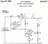
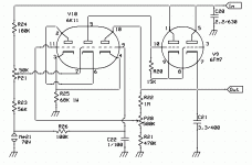
What I want to do is to measure the output impedance of the regulator depicted in the next schematic. It appears to be complicated because of my way of drawing the tubes, but essentially it is quite simple. The 6K11 has 2 hi µ triodes (Like a 12AX7) wired as a cascode, and a medium µ like a 6C4 or half 12AU7 in the same envelope. The medium µ is a cathode follower from the neon lamp reference, slightly filtered, and whose anode current is about 1mA, while the cascode is about 100µA, so the follower current clearly dominates cathode's node voltage. The 6FM7 has a hi µ unit acting as a active load for the cascode and also attacks in low impedance the grid of the lo µ unit, in such a way that if the load is high and input voltage is low, its grid may draw current from the hi µ and still maintaining hi impedance to the cascode DC amp and maintain regulation, a thing that I had proved to be of good performance, and that I learn in the US patent below to be done some years ago. I use a bit different topology in my project. The voltage sensing attenuator is wired to the bottom cascode grid with a net gain estimated of to be above one thousand times.
The point actually resides in the top grid of the cascode. It is feed from a voltage divider from input side of the regulator, and this way one can inject input voltage variation in the circuit without passing through the regulator, and compensating such variations in advance. All the facts descripted here, was read from an old article from M. G. Scroggie in the part II of an article entitled "Stabilized Power Supplies" in the Wireless World in the issue October 1948 page 377 magazine actually scanned and filed in THE HISTORY OF RADIO documented in thousands of PDF books and magazines where it can be read and downloaded for free. Scroggie uses in this item ,a pentode but I want to try my version with cascode, substituting µg2-g1 for bottom µ and µg2 plate for top µ values. A variation of the same idea is being now used in some buck switching regulators like ST's L4971 and many other.
As the author said, there is a point of the adjust of such value that you can compensate exactly for line variation, a further adjust permits you to vanish the regulator's output impedance, and still further adjust enables to vanish also rectifier's and filter's resistance, with a slightly overcompensation of the line regulation. In my case, I prefer the last situation, say, null output impedance (Or slightly negative) over good line regulation. So I want to know the best way to directly measure it while adjusting my P21 preset.
All suggestions are welcomed.
Attachments
Last edited:
Complete: run it at all likely load currents and inject AC signal to the output. The output impedance will change with pass-tube current. The output impedance will be different at all frequencies.
I do something similar to find the optimum load impedance on RF power amplifiers, its called a LoadPull, you basically connect a remotely controlled amplifier at the output and sweep the Smith Chart with it.
I connect a KT88 as a triode, with the control grid connected to a bench power supply, and use it as an active load. Then I can measure voltage and ripple at a range of DC currents, just by adjusting the grid voltage of the KT88. If you need to sink more than 40W, you can add another tube, or add resistors in parallel or series with the tube. You can use the results of this testing to compute impedance.
Note: I probably wouldn't buy tubes to do this, I only use this method because it's possible with junk I have laying around. You probably have junk laying around you could use to accomplish the same thing - be creative.
Note: I probably wouldn't buy tubes to do this, I only use this method because it's possible with junk I have laying around. You probably have junk laying around you could use to accomplish the same thing - be creative.
Why does it even matter? A sufficiently large rail cap will give low-enough impedance over the audio band. Tube amplifiers (I assume what you want this for) rarely need extreme low DC impedance because they are not DC coupled.
Quite frankly, I haven't seen a stability issue in the tube regs I have built, but definitely see it in solid state regulators. Of course, for tube amps it could be an issue. Big cap becomes inductive above a few kHz.
Output impedance and stability are, to a pretty good approximation, related by the Erickson Maksimovic equation:
Phase Margin =~ 50.36 × Q^-0.907
You can calculate "Q" by hand, or from Tg with a network analyzer.
It works until Q becomes lower than 0.5 at (which point the regulator may be over-damped.)
A transistor will far outperform a tube in this role. I used 2 2N5551 to provide a noiseless power supply for 2 6922 tubes. Ripple noise is well below the johnson noise from the tube.
155v in from Voltage tripler 2.5v p-p ripple >> 143v out no ripple. base emitter capacitor .01uf eliminates HF oscillations.
Your supply impedance is equal to the Xc of your reservoir capacitor. if it is 100uf the Xc is 13.26 ohms at 120 Hz.
155v in from Voltage tripler 2.5v p-p ripple >> 143v out no ripple. base emitter capacitor .01uf eliminates HF oscillations.
Your supply impedance is equal to the Xc of your reservoir capacitor. if it is 100uf the Xc is 13.26 ohms at 120 Hz.
Last edited:
...Erickson Maksimovic equation
We shouldn't need a Y2K formula for a technology which has been well-proven for 80 years. It may give insight; but probably not real improvement.
Tube regulators are stable because we can't afford to get the insane gain of transistors.
...Big cap becomes inductive above a few kHz.
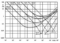
Modern big caps hold very low impedance to above the range of gain of broadband tube amps. See attached. If a 100uFd cap is good-enough at 100Hz, then it is good-enough to past 100MHz. (Assuming very short connections.)
Attachments
We shouldn't need a Y2K formula for a technology which has been well-proven for 80 years. It may give insight; but probably not real improvement.
Tube regulators are stable because we can't afford to get the insane gain of transistors.
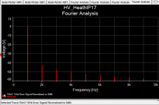
Do this experiment -- resistively load a tube regulator to 25mA -- put a 1kHz 100mV signal on the load and run an FFT.
Do this experiment -- resistively load a tube regulator to 25mA -- put a 1kHz 100mV signal on the load and run an FFT.
and here's what happens with a tube regulator -- the error/control amplifier isn't fast enough to keep up with modulation of the output so harmonics occur on the B+. If you have a regulated stage with poor PSRR it's going to be affected by these harmonics. (Note the scale is dBr 10mV)
Attachments
- Status
- Not open for further replies.
- Home
- Amplifiers
- Power Supplies
- The best method for measuring output impedance