Hello All,
After my Aleph Ono (finished 5 years ago) and Aleph 2 monoblocks (finished 4 months ago) I am ready for my next project, which is to become a Preamplifer / DAC combo. In this thread I would like to focus on the design of the Preamplifer part; the rest is to be done later and is in principle an independent section.
Through a good friend of mine, I got a nice collection of Germanium transistors: both signal and power devices, which are types that seem to be quite popular in audio equipment (mostly guitar amplifiers). These are the original devices made in the early '70-s.
Perhaps less convenient is the fact that they are all P-type transistors, and I have only 4 types available in limited quantities (but sufficient to make a few matched pairs):
- AC125 (Vce=12V, hfe=50 @ 2mA, TD=500mW @25C)
- AC128 (Vce=16V, hfe=125 @ 50mA, TD=700mW @25C)
- GD170 (Vce=30V, Ic=3A, hfe=110, TD=6W)
- GD241B (Vce=40V, Ic=3A, TD=10W)
Information on these devices is quite scarce; only datasheetarchive has some info on the AC125 and AC128 devices. Netlist provided me some data on the GD's. I intend to put the devices on a curve tracer anyway to get some "real life" data, but this will most likely result in a better setting of bias currents.
For now, I am drawing the schematics in terms of architecture. I would like to get your inputs on how to keep the design as close as possible to the "Aleph" mindset, while porting the design to Germanium BJT devices.
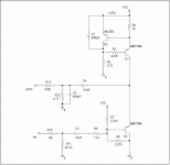
Below is my first iteration: It is mostly derived from the Aleph P so far, but it is my intention to arrive on a balanced design, for example Aleph L. I was thinking to take things step by step, knowing that I am limited to P devices only.
Your inputs are appreciated!
Bouke
So here is: The first iteration of "Aleph Ge"
Attachments
Hmmm... no responses at all... Is that a bad sign?
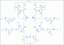
All right then, let's up the stakes a bit... I've made a quick lookover and transferred it into a balanced version... A bit like Aleph P, but without the lower current sources... I've replaced those with a resistor.
All right then, let's up the stakes a bit... I've made a quick lookover and transferred it into a balanced version... A bit like Aleph P, but without the lower current sources... I've replaced those with a resistor.
Attachments
No, I was hoping to get some gain... In the order of 17 - 20dB. It is supposed to be followed by a relay attenuator circuit.
Most of the resistor values are quite preliminary so far... I need to measure a few transistors to get Vbe data and such. I haven't been able to simulate the circuit in SPICE so far.
I suppose then the mistake is in the lower transistor. I tried to transport the Aleph L (v1.0) design to PNP transistors... The CCS in the Aleph L is P-channel and PNP, but the gain device is N-channel.... I guess I biased it wrong?
CCS-es down , active up ;
that way you'll have gain
(if load (CCS) is in emiter , you have no gain )
that way you'll have gain
(if load (CCS) is in emiter , you have no gain )
I can easily see advantages in certain circumstance for changing
the comparator over to germanium. The lower threshold voltage
of the germanium emitter can make for a very low dropout CCS.
Or emitter coupled base follower with a very low voltage offset.
But I can't as easily make a case for changing the power device
over to germanium. MOSFET and/or IGBT rule that department.
Leave well enough alone. But if you must go there, there is a
thread by Keantoken in the solid state area. I believe the Aleph
MOSFET is replaced by Sziklai pair, he was calling that "Allison".
I don't know any history on the Allison circuit.
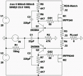
I'll abuse one of my old schematics for example, chosen mostly
for sake of simplicity: If germanium thresholds had been used
here, much smaller quiescent set resistors would be needed.
With a resulting increase in damping factor.
I have both NPN and PNP germaniums, but they are far from
"complimentary". I did do some cherry pick HFE matching, but
not sure if the meter I borrowed that day was appropriate
for measuring germanium HFEs. Probably doesn't matter in
this application anyway, only the emitter's forward voltage.
Attachments
- Status
- Not open for further replies.


