So, I've been playing around with various DACs recently and found there's actually quite a lot of difference between those usual suspects. I'd really like to give an R-2R ladder a try, but the PCM1704 is a bit pricey. It got me thinking though, whether it's worth that kind of money and whether R-2R DACs can really be better than Sigma-Delta, etc.
So, to find out where we stand, I whipped up a simple 16-bit R-2R DAC from the cheapest resistors I had around, driven from 72HC595's that are fed from a CPLD which does the data conversion after my Amanero USB-I2S module. And yes, I can confirm, it sounds absolutely horrible. Worse than I thought possible in fact. I expected a significant level of noise as there is no shielding whatsoever and a lot of gadgets in the immediate vicinity of the circuit. That sort of noise isn't so bad though, the worst is really the non-linearity of the DAC, which I found particularly disturbing when listening to spoken language. Anything that uses distortion on the guitars sounded pretty OK in fact.
Of course, I couldn't leave it at that and decided to try a better R-2R DAC. Once you've reached that point, the decision is really between buying a super expensive out-of-production beast like the PCM1704 or buying a lot of super expensive .01%/matched resistors. I didn't like either of those options and looked into building my own high-precision resistors, which isn't quite such an attractive option either, and, essentially, you end up with a big box of inductors.
It did set my mind onto resistance wire though and, instead of winding my own resistors, I worked out a way to wind a whole DAC from a single piece of resistance wire. I purchased various kinds of resistance wire off of ebay; the one I ended up using is Constantan (Isostan brand), .05mm/44AWG. I also considered Nichrome and Manganin, they are available in smaller gauges and higher resistances, but harder to solder. Anyways, .05mm is thin enough, trust me. I ended up covering the PCB in yellow masking tape so that I had a light background against which I could, at least sometimes, through my magnifying glass, see the wire.
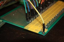
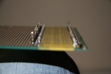
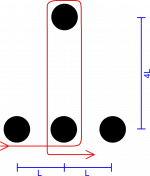
The way I set it up is to solder little metal posts to a perfboard in the right pattern; 3 holes distance between the rungs and 12 holes rung length (4 times the rung distance). This way I can run the wire from one rung to the next and then up and back down again. I attached a diagram to explain that part better. When using resistance wire, distance is essentially the same as resistance, thus I have a 1R resistance between rungs and the rung length is 4R in parallel with another 4R wire, yielding the required 2R. I managed to take a couple of photos of the finished product and in which you can see the wire. It's indeed made from a single piece of Constantan running from the ground post (yellow wire) all the way up to bit #16 and the output wire (orange), which went into a voltage follower opamp to keep the current in check.
Admittedly, this is a bit crazy, but it actually works. The Constantan I used is rated 250 Ohm/meter and the rungs are separated by about 7.68mm which means roughly R=2 Ohms. On paper, that sounds a bit low, but I managed to get it playing for about half an hour without burning the wire. I guess this might also depend on what you use to drive it and what kind of opamp you feed it into. There is of course the possibility to simply make it larger if that's a concern. There's also the possibility to build several of them on the same board and posts, essentially getting an averaging effect like in those DAC stacks... Oh my, I see a lot of very thin wire in my future.
So, how does it sound, I hear you ask? Still pretty noisy; it's a fantastic antenna! Apart from that however it sounds pretty good. It's definitely a _lot_ less non-linear compared to the cheap 5%-R-2R ladder I tried before. I couldn't find any problems with non-linearity whatsoever, in that respect it really surprised me. But the noise is still too bad to really compare it to a real DAC. I am thinking about potting it with epoxy and covering it with foil though...
Anyways, let me know what you think. I'd be super interested in hearing about similar experiments that you have done. If you want to wind your own 1-wire DAC, I'd be happy to help! I should perhaps add that it's not actually required that you build it from a single length of wire, many small segments work just as well, but you need to be better than me with the soldering iron.
So, to find out where we stand, I whipped up a simple 16-bit R-2R DAC from the cheapest resistors I had around, driven from 72HC595's that are fed from a CPLD which does the data conversion after my Amanero USB-I2S module. And yes, I can confirm, it sounds absolutely horrible. Worse than I thought possible in fact. I expected a significant level of noise as there is no shielding whatsoever and a lot of gadgets in the immediate vicinity of the circuit. That sort of noise isn't so bad though, the worst is really the non-linearity of the DAC, which I found particularly disturbing when listening to spoken language. Anything that uses distortion on the guitars sounded pretty OK in fact.
Of course, I couldn't leave it at that and decided to try a better R-2R DAC. Once you've reached that point, the decision is really between buying a super expensive out-of-production beast like the PCM1704 or buying a lot of super expensive .01%/matched resistors. I didn't like either of those options and looked into building my own high-precision resistors, which isn't quite such an attractive option either, and, essentially, you end up with a big box of inductors.
It did set my mind onto resistance wire though and, instead of winding my own resistors, I worked out a way to wind a whole DAC from a single piece of resistance wire. I purchased various kinds of resistance wire off of ebay; the one I ended up using is Constantan (Isostan brand), .05mm/44AWG. I also considered Nichrome and Manganin, they are available in smaller gauges and higher resistances, but harder to solder. Anyways, .05mm is thin enough, trust me. I ended up covering the PCB in yellow masking tape so that I had a light background against which I could, at least sometimes, through my magnifying glass, see the wire.
The way I set it up is to solder little metal posts to a perfboard in the right pattern; 3 holes distance between the rungs and 12 holes rung length (4 times the rung distance). This way I can run the wire from one rung to the next and then up and back down again. I attached a diagram to explain that part better. When using resistance wire, distance is essentially the same as resistance, thus I have a 1R resistance between rungs and the rung length is 4R in parallel with another 4R wire, yielding the required 2R. I managed to take a couple of photos of the finished product and in which you can see the wire. It's indeed made from a single piece of Constantan running from the ground post (yellow wire) all the way up to bit #16 and the output wire (orange), which went into a voltage follower opamp to keep the current in check.
Admittedly, this is a bit crazy, but it actually works. The Constantan I used is rated 250 Ohm/meter and the rungs are separated by about 7.68mm which means roughly R=2 Ohms. On paper, that sounds a bit low, but I managed to get it playing for about half an hour without burning the wire. I guess this might also depend on what you use to drive it and what kind of opamp you feed it into. There is of course the possibility to simply make it larger if that's a concern. There's also the possibility to build several of them on the same board and posts, essentially getting an averaging effect like in those DAC stacks... Oh my, I see a lot of very thin wire in my future.
So, how does it sound, I hear you ask? Still pretty noisy; it's a fantastic antenna! Apart from that however it sounds pretty good. It's definitely a _lot_ less non-linear compared to the cheap 5%-R-2R ladder I tried before. I couldn't find any problems with non-linearity whatsoever, in that respect it really surprised me. But the noise is still too bad to really compare it to a real DAC. I am thinking about potting it with epoxy and covering it with foil though...
Anyways, let me know what you think. I'd be super interested in hearing about similar experiments that you have done. If you want to wind your own 1-wire DAC, I'd be happy to help! I should perhaps add that it's not actually required that you build it from a single length of wire, many small segments work just as well, but you need to be better than me with the soldering iron.
Attachments

I like your, hmm, alternative way of doing a R2R dac 🙂
The question is, what do you drive it with, 2 ohm is kinda a pretty low impedance ?
But t.ex. Digikey have pretty good stock of precision smt resistors at good prices, it's probably easier to hand solder tiny smt resistors than messing with resistance wire....
Also, try a sign magnitude version, lower the requirement for precision of the resistors, except the ones used for the +- reference.
Me, I'm a smt guy, and right now I'm actually waiting for my new 28 bit sign magnitude R2R dac to come back from the assembly shop.... More on that in a couple of weeks.
Regards,
Soren
I have the discrete Monica bought from yeo at diyparadise .
I think you are trying something very similiar .
It uses smd resistors and sound very nice
I think you are trying something very similiar .
It uses smd resistors and sound very nice
You could place a copper foil underneath that yellow tape... and connect it to a good ground...
1704 demands very low ground plane noise, low noise power supplies, and with only 2mA on a good day of output - it also demands a seriously good I/V - hence why 1704 implementations sound good.
With the same amount of care taken, other DAC's can sound excellent as well.
I personally like 1704 because it does not colour the sound in any way. It presents the recording it its true light, for good or for the bad...
Nick
I tried a 2R-R dac with 0.1% 100k resistors, where I added 100R trimming variable wirewound resistors to the six MSBs. Also important is the switching element, I used complementary MOSFETs with 0.1/015 ohm Rdso. But the glitch problem still remains. It worked but I did not conclude any critical listening.
I also have an idea in my mind: using a transformer (á la TVC) with 16 taps, where the turns ratio is 1:1:2:4:8:.....:32768. It seems not quite impossible to wind 65536 turns, and linearity would be guaranteed.
I also have an idea in my mind: using a transformer (á la TVC) with 16 taps, where the turns ratio is 1:1:2:4:8:.....:32768. It seems not quite impossible to wind 65536 turns, and linearity would be guaranteed.
I will use two banks of LVC595's, they have about 13R output impedance, which I have verified by testing some samples. Then two R-2R networks with 4K99 and 10K0 || 3M01, to adjust for the driver output impedance, connected so they work as a sign magnitude DAC to avoid the MSB switching issues with a regular R-2R DAC. That will also avoid glitch problems, as the MSB are only switching when needed. Using lower value resistors also improve speed and lower the noise, calculating without output buffers gives about 129 db S/N.... Not that you can hear that, but it leaves plenty of headroom for digital volume control...
I would also said using mosfet drivers with 0.1R/0.15R rdson is way overkill, especially with 100K 0.1% resistors, as the resistors themselves are only precise to 100R....
Soren
I would also said using mosfet drivers with 0.1R/0.15R rdson is way overkill, especially with 100K 0.1% resistors, as the resistors themselves are only precise to 100R....
Soren
What would be the architecture of a sign-magnitude DAC using two discrete converter ?
Something inspired by the PCM1704 ?
As far as I know, the PCM1704 uses two DAC.
The first is in charge of the negative current (say from -Iref to 0) while the first is inactive. The second is in charge of the positive current (say from 0 to +Iref) while the first is inactive.
With a discrete R-2R based on LVC595, I guess it's a voltage DAC. However, I don't see a proper and simple way to have this same behaviour (probably by adding the two discrete DAC and adding -Vref to the sum output ?). Or I may have overlooked something as well.
- Status
- Not open for further replies.
- Home
- Source & Line
- Digital Source
- The 1-wire DAC