Hello,
after some time I decided to upgrade my Wadia 3200 drive with a Tentlabs XO3.2 Clock.
Although I know how to connect the clock, but how and where I now exactly the S / PDIF signal must grab to reclock it, I'm a bit unsure.
A 74HC244N chip is installed on the digital output board (photo).
As I understand it, I separate PIN14 from the board and then connect PIN14 with the reclock-module.
The Tentlabs installation guide is not quite unambiguous on this point.
Can anyone tell me if this approach is correct?
Regards
Achim
Attachments
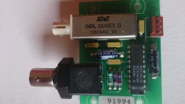
You can intercept the Wadia's SPDIF signal before it reaches the 74HC244N chip. My guess is that the signal is sent to the output board (photo of which you provided) on one of 4 wires that attaches to the board via the red connector. The other 3 wires probably are V+, Ground/0v and clock signal.
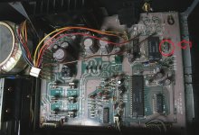
You will need trace the tracks on the pcbs to find the signal carrying wire. If you do that, you can leave off the entire output board. You then can connect a new chassis mounted connector on the Wadia (75ohm BNC is best) to which you connect the Tent clock's SPDIF output to.
Cheers,
David
You will need trace the tracks on the pcbs to find the signal carrying wire. If you do that, you can leave off the entire output board. You then can connect a new chassis mounted connector on the Wadia (75ohm BNC is best) to which you connect the Tent clock's SPDIF output to.
Cheers,
David
- Status
- Not open for further replies.