Hi.
I find that some of my projects end up needing a fan.
My last amplifiers have run from +/-60V and the fans mostly run of 12V.
To keep them quiet I like run them around 10V, but in any case they cannot run from 60V.
I would like a temperature-controlled switch and I would like to avoid the massive loss from a linear regulator from 60V.
So we have two challenges: a buck-regulator that will drop 50V with low loss and a temp-controller.
The simplest fan-controller I can find on the www is from Mark Hennesy:
Micro-Amp › Circuit Design
I know that integrated SMPS-controllers exist that will do the job, but I did not have any and I wanted a solution that is widely availible.
A search revealed that a very simple circuit was maybe enough (Google: "dsicrete buck converter".
circuit analysis - DC-DC Buck Converter Issue - Electrical Engineering Stack Exchange
So the building-blocks look simple, - i "just" had to connect the two...
That proved a little complicated, and also I wanted to use a N-channel-FET as those are cheaper and already in my stash. luckily a discrete solution is easily mirrored to use N- instead of P-channels.
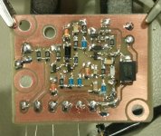
After a few iterations I ended up with the attached schematic.
A few notes:
Prototype draw around 40mA from 60V when supplying a fan around 10V@200mA. Mosfet and coil is warm, but far from dangerous.
I'll share an single-sided PCB if there is any interest (and the prototype behaves)
What do you think?
Kind regards TroelsM
I find that some of my projects end up needing a fan.
My last amplifiers have run from +/-60V and the fans mostly run of 12V.
To keep them quiet I like run them around 10V, but in any case they cannot run from 60V.
I would like a temperature-controlled switch and I would like to avoid the massive loss from a linear regulator from 60V.
So we have two challenges: a buck-regulator that will drop 50V with low loss and a temp-controller.
The simplest fan-controller I can find on the www is from Mark Hennesy:
Micro-Amp › Circuit Design
I know that integrated SMPS-controllers exist that will do the job, but I did not have any and I wanted a solution that is widely availible.
A search revealed that a very simple circuit was maybe enough (Google: "dsicrete buck converter".
circuit analysis - DC-DC Buck Converter Issue - Electrical Engineering Stack Exchange
So the building-blocks look simple, - i "just" had to connect the two...
That proved a little complicated, and also I wanted to use a N-channel-FET as those are cheaper and already in my stash. luckily a discrete solution is easily mirrored to use N- instead of P-channels.
After a few iterations I ended up with the attached schematic.
A few notes:
- If the circuit do not oscillate it can in some cases regulate linearily. It may produce an output voltage, but the dissapation is much to high
- The feedback-capacitors C2 and C7 may need some trimming to optimize performance and achieve stable regulation
- Two feedback-options are availible: throug C2 or C4. I still dont know whats best.
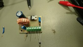
- I have used a coil from the junk-box around 200uH. The value do not appear to be critical.
- losses in the inductor may be enough to heat it up. Try different alternatives.
- Be aveare that T2 and Q3 see the full input voltage. use 100V devices for 60V supply
- Notice that the fan-output is NOT regulated relative to GND, but to Vcc. That should not be a problem for an insulated plastic-fan.
- D1, D2 and D6 are 10V zeners
- D3 is a low-voltage fast diode
- D4 is a 100V fast diode
- R5 sets temperature-trig point. May be replaced with R9 when the value is found.
Prototype draw around 40mA from 60V when supplying a fan around 10V@200mA. Mosfet and coil is warm, but far from dangerous.
I'll share an single-sided PCB if there is any interest (and the prototype behaves)
What do you think?
Kind regards TroelsM
Attachments
First error spotted: Emittor of T2 is the feedback and should be connected AFTER the inductor: at the junction of L1 and C10. Otherwise the circuit will operate linear.
Kind regards TroelsM
Kind regards TroelsM