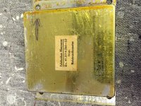
I have just received this stereo from my father. He bought it in the 60s when he was stationed over seas. It has been working until a couple years ago when it started blowing fuses. I have isolated the transformer as bad but I can't tell what the three voltage outputs are.
I have attached pictures of the transformer as well as a scan of the original wiring diagram. Does anyone have any suggestions?
I have attached pictures of the transformer as well as a scan of the original wiring diagram. Does anyone have any suggestions?
Attachments
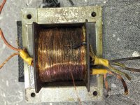
It is clearly blown.
If you know the input voltage, a guy who has experience re-winding transformers, only counting the turns is capable of doing a new exact replica. But before doing it, be sure that it isn't a shorted cap in the rectifier or another component faulty that, then, blown the new unit.
If you know the input voltage, a guy who has experience re-winding transformers, only counting the turns is capable of doing a new exact replica. But before doing it, be sure that it isn't a shorted cap in the rectifier or another component faulty that, then, blown the new unit.
Last edited:
The two sets of filament windings are 6.3V around 2A each (check filament current!) , and for the high voltage winding I believe it was in the vicinity of 140V/150mA. Look on eBay and see if you can find a replacement, alternatively depending on budget you might be able to get it rewound. (Probably not worth the expense.)
I would guess that a short or partial short in the bridge rectifier or one of the filter caps was responsible for the destruction of the power transformer.
I would guess that a short or partial short in the bridge rectifier or one of the filter caps was responsible for the destruction of the power transformer.
Thanks for the quick reply! I know the input voltage (120V). I think it might have gone out due to the fact that my father never switched the input voltage back to 120 when he came back to the states. He was running 120v thought the 240v input on the transformer for years. I just don't know how to tell what the output voltages should be. There are three outputs, one to the rectifier and two others as seen on the diagram.
I don't believe you. No one equipment will work reasonably well with half the power supply, more over if it has tubes in it. No one tube will perform with half voltage in its heater. And if it would be certain, half a voltage in the primary winding isn't a good reason for it blown. The vice versa is always true (twice the voltage will catch fire any transformer quickly).
Last edited:
I enlarged the PDF view, to see what the schematic shows. I see 260 V. and 100 uF. at the 1st filter capacitor. A 200 VRMS rectifier winding seems about right. If it can be mechanically "shoehorned" in, a modestly priced AnTek AS-1T200 should prove satisfactory. Lots of trash rides on today's AC mains. Mount ferrite beads on the primary wires, to suppress the garbage. Toroids are wide bandwidth.
Replace ALL electrolytic capacitors. Replace the bridge rectifier with 4X UF4007 diodes. Even if the OEM part is still "good", it's likely to be ticking, toxic, time bomb selenium.
Replace ALL electrolytic capacitors. Replace the bridge rectifier with 4X UF4007 diodes. Even if the OEM part is still "good", it's likely to be ticking, toxic, time bomb selenium.
I promise that it was never switched. I would not get good advice if I was not giving actual information. I switched it myself a month ago when I first started looking at it. I don't know why it worked for so many years. My thought on the lower voltage was the same as yours. I will check the rectifier and caps as well. I am an hvac master technician by trade and trouble shoot and repair very complex air conditioning circuits so I am familiar with diagrams and circuits but I am out of my element with the radio circuits. That is why I am reaching out to this forum for help as this is my first stab at a new interest.
You are in wright place.
OK, perhaps another person moved the switch previously. Try to run an air conditioner, a fridge or a simple lamp with half the power supply, it won't run correctly. Or it doesn't do it at all.
OK, perhaps another person moved the switch previously. Try to run an air conditioner, a fridge or a simple lamp with half the power supply, it won't run correctly. Or it doesn't do it at all.
Eli - Thanks for the reply I think I will replace the rectifier as you suggest. So both of the other secondary outputs would be 6.3v / 3a as on the transformer that you recommended?
I have ordered the parts. I will post back when I get it together.
Thanks for your patience and quick replies.
Thanks for your patience and quick replies.
The suggested toroid replacement transformer should work electrically and is probably the most cost-effective solution, but it may be difficult to bolt it to the chassis. Both low voltage windings are 6.3v: the dial lamps are often specified 7v altough the supply is 6.3v. The origina high voltage winding should be 240V (this was the value on the majority of ECL86 equipped radios), but the silicon rectifier is more efficient than the original selenium rectifier and the original transformer had a comparatively high winding resistence compared to the modern replacement so 200-220v should be ok. The charred transformer is often caused by a shorted selenium rectifier, or by overload on the main high voltage line, such as a degraded capacitor. Replace at least the first electrolytic C701 and possibly all of them. Use a 400 or 450V rated capacitor; with the brand new silicon rectifier (you may use a bridge) and a modern transformer you may safely increase the capacity to 220uF or maybe 470uF. Replace both coupling capacitors on the output tube grids (C309 and C1309). A electrically leaking coupling capacitor will increase the current consuption of the output tubes and may overload the power supply and the power supply resistors (check R701, R1701, R702 and R703 for drifted values). It will also lead to premature output tube failure, and your ECL86/6GW8 tubes aren't cheap to replace - but they may be substituted with PCL86 / 14GW8 by changing their filament supply voltage. ECL86 tubes (6.3V filament) are commonly installed in high quality tube radios and small amplifiers, while PCL86 (14v filament) are a very common B&W TV tube. Production of both tubes ceased decades ago but the stock of PCL86 is still plentiful while the NOS ECL86 stock is almost depleted. I believe this chassis does use a early printed circuit boards, brown color. They are extremely fragile, set the soldering iron to a low temperature and avoid the lead free solder wire. Hairline cracks and detached PCB tracks are a very common outcome. Use plenty of contact cleaner spray on the switches.
This a pretty large floor standing console so there is a ton of space so mounting of the new transformer will not be an issue. and yes it has the old printed circuit boards. I am wondering if I might be getting in over my head as I do not have a delicate hand with a soldering iron!
I tried to find someone that I could hire to work on it for me but have had no luck in the San Antonio area. That said, it looks like I am on my own.
All of the excellent advice on this site makes me a little more comfortable.
I tried to find someone that I could hire to work on it for me but have had no luck in the San Antonio area. That said, it looks like I am on my own.
All of the excellent advice on this site makes me a little more comfortable.
I finally have enough time to start tackling this project. Have the new transformer but would love recommendations on which rectifier to purchase.
On my restorations I use a 800v 6A or 10A bridge rectifier with flat body and hole mounting such as the 4gbj-608 or 4gbj-1008 , because is easier than smaller or prismatic types to mount at the same place of the original selenium rectifier. If you replace a selenium rectifier with a silicon rectifier, you will increase the output DC voltage. To compensate for this, put a RC cell after the rectifier: 47 or 100 uF 450V electrolytic capacitor directly at the + terminal of the new rectifier togheter with one lead of a 300 ohm 5W resistor; the wire that was connected to the + terminal of the original selenium rectifier should go on the other side of the resistor. The exact value of the resistor should be adjusted to give the HT voltage written on the schematic diagram (plus/minus 5% tolerance). Place a 300mA slow-blow fuse directly in series to one of the HT winding of the transformer, before the rectifier, to protect it from overheating again: the original fault may be the effect of a intermittent short. If the original rectifier is still working I would leave it in place, check if the radio is working with the new transformer, and only then replace the rectifier with the silicon substitute. It is always best to replace a single item at time. I replace the rectifier only if the radio will be used often or if the rectifier is the older cylindrical type. The replacement may reveal hidden grounding or capacitor issues and may ultimately cause motorboating oscillation in the output stage. This will easily be solved if it can be traced to the rectifier installation, but will be more difficult if you change/move several components and wires at the same time.
If your replacement transformer cannot be installed at the exact spot of the old burned one, be aware of the cable routing. On most german radios the power transformer is next to the volume and balance controls. They usually have extremely high impedence and will pick up any stray magnetic field from the transformer wires and windings. A nasty hum or buzzing sound is the consequence. Route the transformer wires away from the controls and the preamp tubes, and respect the original grounding points on the chassis.
If your replacement transformer cannot be installed at the exact spot of the old burned one, be aware of the cable routing. On most german radios the power transformer is next to the volume and balance controls. They usually have extremely high impedence and will pick up any stray magnetic field from the transformer wires and windings. A nasty hum or buzzing sound is the consequence. Route the transformer wires away from the controls and the preamp tubes, and respect the original grounding points on the chassis.
- Status
- Not open for further replies.
- Home
- Amplifiers
- Tubes / Valves
- Telefunken Princess II 5486MX transformer question