First of all I'm new to this forum and I hopei put this in the right channel.
I recently acquired a used tektronix type 564 oscilloscope. I'm starting my electrical engineering course after the summer break and I wanted a oscilloscope that I could use at home (and which I could easily service).
The issue is that I do not want to spend too much money because I dont have a lot replacing almost every part inside the oscilloscope, only the defective ones.
So the tube oscilloscope's voltage rails sag a lot when both plugins are in the oscilloscope (Vertical 3A74 and horizontal 3B4). But when I plug each of them in individually the oscilloscope's voltages are fine. Furthermore with both of them in the OG3 neon regulator tube does not loght up as compared to them being in in the machine seperatly.
What also is a weird thing is that the neon bulbs between G1 and the cathode of the CRT light up when there is 1 plugin inside it (and also when theres none).
So, I assumed the filter capacitors were problably at fault. After checking them they were fine but the values were wrong. The schematic points to using a 350uF + 10uF can capacitor meanwhile my capacitors were 160uF and 10uF capacitors.
Would this be the issue? Or is there problably some other underlying problem?
TLDR: Oscilloscope has wrong voltages and weird value caps, does that matter?
564 was tube based, 564B was SS. Sounds like a power supply problem. An old tube based model probably has 1000s of hours on it. Typically there was one main regulated supply, and the other supply regulators used that as their V reference. Start by testing any rectifier tubes, Then work thru the tubes in the main supply, followed by the other V supplies. Check electrolytics. Look for any burned parts. Once the supply voltages are working, plug the plug-ins in repeatedly (power off! ) to clean up the plug contacts.
manuals:
https://w140.com/tekwiki/wiki/564
manuals:
https://w140.com/tekwiki/wiki/564
I checked the diodes which all work test fine on a Vdrop diode multimeter (they are silicon its a hybrid oscilloscope). The big electrolytics also check out, their ESR is fine and capacitance is in spec. But like I said the capacitances are different in my scope compared to the schematic. So would instead of a 350uF capacitor a 160uF capacitor make it so that the rest of the system cannot handle the load?
Tomorrow i'll check the regulator circuitry, but I do want to say that under a lesser load it does regulate fine.
Tomorrow i'll check the regulator circuitry, but I do want to say that under a lesser load it does regulate fine.
There may be a regulator tube that has dropped to too low a gm to support the required current. See which supply is dropping out and replace the final regulator tube.the rest of the system cannot handle the load?
Type 564 is a lovely instrument and I still use one on my Sunday bench next to a Tek 7904. Plugins can be cheap sometimes and there is even one with 10uV/div. sensitivity, model 3A9. Agree with post 5. Pictures please.
What I did forget to mention is that the filaments also seemed to burn dimmer with both plugins installed compared to without, especially the graticule lights. The transformer doesn't heat up though so there is no strain on it.
A trace also only appears without or with one plugin in. With both it just dissapears.
It's real late here so I'll provide photos somewhere tomorrow or the day after. Thanks for all your guys help by the way!
A trace also only appears without or with one plugin in. With both it just dissapears.
It's real late here so I'll provide photos somewhere tomorrow or the day after. Thanks for all your guys help by the way!
Last edited:
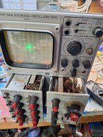
Like I promised here are some pictures


These are with both plugins and the following images are with just one plugin, and the neon bulbs that ignite between the G1 and the cathode of the CRT:


If you need any specific measurements I'll be sure to take them. I have a DMM capable of measuring to 600v DC max. And I have a spectrum analyzer but I doubt that would have any use, and I also have a HP frequency generator 0.001Hz till 50Mhz.
These are with both plugins and the following images are with just one plugin, and the neon bulbs that ignite between the G1 and the cathode of the CRT:
If you need any specific measurements I'll be sure to take them. I have a DMM capable of measuring to 600v DC max. And I have a spectrum analyzer but I doubt that would have any use, and I also have a HP frequency generator 0.001Hz till 50Mhz.
Wow! Are those nuvistors in photograph 2 or early transistors? (I suspect early transistors.) That glowing protection neon in photograph 3 must be a clue, it's hard to tell for certain, but it looks as though it might be in the power supply department. Tek oscilloscopes tended to have one main regulator that was used as a reference for others, so that's the place to start looking. Good luck.
Those are actual nuvistors funnely enough the 7586. Might out of spec resistors in the psu cause a voltage sag aswell? Or is it more often bad tubes and capacitors? I'll check everything tomorrow.
Instead of speculating have a look at the supply voltages.
https://w140.com/tekwiki/images/a/ae/Tek_564_power_supply.png
In the last picture I see two HongKong capacitors, so have a close look at previous repair attempts.
https://w140.com/tekwiki/images/a/ae/Tek_564_power_supply.png
In the last picture I see two HongKong capacitors, so have a close look at previous repair attempts.
Last edited:
Ok so basically after the regulators the voltage rails drop a lot. 300V+ is now 220V+ and the adjust doesnt change it that much. But what I did discover is that the unreg 420V with both plugins is about 270V and with one plugin is 330V. With no plugins its about 410-420V it flucuates. Also with no plugins a trace appears on screen:
I might add that the 420V is after the filter capacitor which is about 170uF instead of the schematics 350uF. (It has problably been replaced in the past but its ESR and Vloss are fine).
I might add that the 420V is after the filter capacitor which is about 170uF instead of the schematics 350uF. (It has problably been replaced in the past but its ESR and Vloss are fine).
Attachments
Yes, it could be. The regulator almost certainly has a 6080 as a series pass device and it will probably have 100 ohm anode stoppers. Try measuring the voltage across one of those stoppers as a means of determining how much current the regulator is supplying. Beware that there should be 420V there. In the unlikely event of there being a large voltage across the 100 ohm, the supply is being dragged down, but it's more likely that the reservoir capacitors need replacing.
You can see that there are two raw dc supplies in series so it is easy to check in which half (C642a or C644a) the sag is. With input of 270V 6AS7 tube can not supply 300V output. Look at the supply schematic (post 11).
Tektronix regularly used 10Ω resistors at the output of the rectifiers of each of the high voltage supplies as an inexpensive fuse in order to protect the transformer windings in the event of a filter capacitor failure, and as an easy way to measure the current being supplied to individual circuit areas.
These will often increase in resistance after decades of service/abuse.
These will often increase in resistance after decades of service/abuse.
Ok so I checked post 17 and post 16's questions. The 10 ohm and the one 100ohm resistor all measure in spec, so that'd be unlikely. The C644a does sag aswell as the 642a. Although it then means that C642A is the trouble causer right? Because it doesn't elevate the voltages enough for C644a?
The capacitor specs are in order but the capacitance is 160uF instead of the desired 350uF (the capacitor is rated for 160uF). The other capacitor C644a is 125uF + 125uF in my circuit, but in the schematic its also 350uF so would both of them need to change?
By the way I do not have a tube tester or a spare 6AS7, I could buy one but if I don't need to I'd much rather not. I do have spare ecc88 and EF94s.
And to respond to post #15, there are no 100 ohm anode stoppers connected to the 6080/6AS7. There is a 10 ohm anode stopper but thats put before the filter capacitor and measures in spec so that should be fine?
I will measure the voltage across the resistor soon.
I will measure the voltage across the resistor soon.
That was my work, those capacitors looked real bad and measured weird so I replaced them with capacitors I got from a reputable source, these are electrolytics.In the last picture I see two HongKong capacitors, so have a close look at previous repair attempts.
- Home
- Amplifiers
- Tubes / Valves
- Tektronix type 564 tube oscilloscope repair