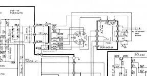
I am about to embark on repairing this amplifier and I have downloaded the schematic from hifiengine https://www.hifiengine.com/manual_library/technics/su-v4.shtml
Looking at the power transformer and rectifier area the centre tap of the transformer secondary is shown connected directly to the -48V rectified output rail. Surely this must be incorrect since it means diodes D404 and D406 are directly across each of the output windings. Normally I would expect the centre tap of the transformer secondary to be connected to the 0V (GND) rail at the mid point of the main filter capacitors C403 and C404.
Can anyone offer an expert opinion?
Attachments
Last edited:
When I attended the course many years ago, that point was made and Japan said it was to allow Authorised Service Centres access to better detail when attending the course, which it did.
Many manufacturers put errors in their schematics to ensure only those who were authorised had access to the real data.
I think we sere sent a bulitin about it as well.
Many manufacturers put errors in their schematics to ensure only those who were authorised had access to the real data.
I think we sere sent a bulitin about it as well.
Thanks for the reply Jon. If manufacturers inserted deliberate errors in their documents and schematics they would be doing their service representatives a great disservice by publishing misleading information which could result in damage to their brand. They probably gave the excuse that it was to ensure only authorised representatives were issued with the real data to cover their mistake - and I think it was just that - a mistake.
I note that Technics did not carry over this "deliberate" error to the schematic on the SU-V4X shown below. Here the CT of the transformer secy and the mid-point of the filter caps are both connected to the 0V (GND) rail.

I note that Technics did not carry over this "deliberate" error to the schematic on the SU-V4X shown below. Here the CT of the transformer secy and the mid-point of the filter caps are both connected to the 0V (GND) rail.
