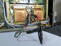
I'm going to attempt to restore this 1977 amplifier that belongs to neighbor,it has been ""fixed"" by a 90 y/o bloke with Alzheimers.lol I'm not kidding! He has cut off all the wires to the voltage adjuster,installed the wrong transistors,etc... and blown it up on both channels.I think I maybe able to fix it but I need a SU-8080-WG. West German schematic of the twin transformer power supply to rewire it back to its original state. I'm in Australia 240v,the schematic I have for the power supply here is SU-8080-XAL.If anyone can help me with this I would appreciate it. The German bloke who owns it has had the complete Technics setup from new including the big Technics reel to reel. I'm sure he would be happy to have it going again.🙂
Attachments
Last edited:
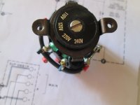
Yes, but there's only one red wire coming from each transformer and five red wire connections on the voltage selector? There are numbers on the selector in the schematic but none on the selector itself so I dont know whats what? I dont want this to become a parts amp for lack of info,I just dont know where to find it though? Technics is a dead end?😕At least you have the wire colours on the old selector to go by.
Good luck.
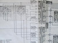
The correct switch position would seem to have been 4.
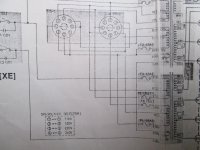
YEL and BLK need to be connected together (on both xfmrs)... and quite possibly that's all that needs to be done, though it would be necessary to see more of what's going on further towards the left to be sure.
YEL and BLK need to be connected together (on both xfmrs)... and quite possibly that's all that needs to be done, though it would be necessary to see more of what's going on further towards the left to be sure.
Here is the rest of it to the left. Orange 0v, red 110v, yellow 120v, black 120v, blue 110v, brown 0v, (brown and green at the end ?) Dont forget that this amp has two separate power supplies.The correct switch position would seem to have been 4.
YEL and BLK need to be connected together (on both xfmrs)... and quite possibly that's all that needs to be done, though it would be necessary to see more of what's going on further towards the left to be sure.
Attachments
Last edited:
The correct switch position would seem to have been 4.
YEL and BLK need to be connected together (on both xfmrs)... and quite possibly that's all that needs to be done, though it would be necessary to see more of what's going on further towards the left to be sure.
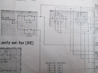
Theres stuff here that I dont understand like is this supposed to be wired for 240 volts off of both transformers or 120v of each? I dont get what the squiggle is between the fuse on the brown and the green wires is either? Ive marked them with an X. Ive never come across any symbol that looks like that?
Attachments

I think 240V wiring for each tranformer,just get the twoo 120V windings in series on each transformer.
and the stuff is a thermal protection,so it should be in series with primary 120V windings
Last edited:
^ What the guy above me said.
This is a dual mono affair with one power transformer per channel, so you need to wire up both transformers up in parallel, with the two 120V windings in series on each of them. (Follow connections for a switch position of 4.) I thought that was obvious but maybe not.
This is a dual mono affair with one power transformer per channel, so you need to wire up both transformers up in parallel, with the two 120V windings in series on each of them. (Follow connections for a switch position of 4.) I thought that was obvious but maybe not.
- Status
- Not open for further replies.
- Home
- Amplifiers
- Solid State
- Technics SU-8080 WG Schematic.