Hi all,
Looking to remove the computer type cable from my BBC technics sp10mkii p/l, now the table in bbc stock form is made up of three boxes, the psu, sh-10e the table the sp10mkii p/l, and also a control box the sh-10c. I want to do away with the control box and restore the start stop function on the deck itself.
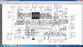
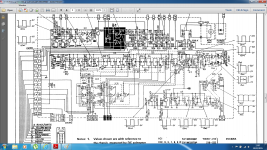
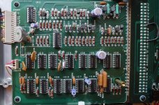
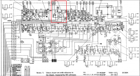
The logic board is where this cable comes from, this comes in many different versions all very similar, the bbc versions have some of the functions of this board outsourced to different boxes. The version I have differs slightly from the original stock domestic sp10 mainly in the parts I have highlighted, other things of note is a redesigned clock circuit and a different layout in some areas but it all seems to correspond between the stock version and mine (the p/l version).
Now my question is if I change the highlighted section on the p/l to the same circuit as the stock sp10 would this restore the start stock functionality of the deck as it was originally intended?
Please see attached schematics, first is the domestic sp10, second is the bbc broardcast p/l version.
Thanks
Chris
Looking to remove the computer type cable from my BBC technics sp10mkii p/l, now the table in bbc stock form is made up of three boxes, the psu, sh-10e the table the sp10mkii p/l, and also a control box the sh-10c. I want to do away with the control box and restore the start stop function on the deck itself.
The logic board is where this cable comes from, this comes in many different versions all very similar, the bbc versions have some of the functions of this board outsourced to different boxes. The version I have differs slightly from the original stock domestic sp10 mainly in the parts I have highlighted, other things of note is a redesigned clock circuit and a different layout in some areas but it all seems to correspond between the stock version and mine (the p/l version).
Now my question is if I change the highlighted section on the p/l to the same circuit as the stock sp10 would this restore the start stock functionality of the deck as it was originally intended?
Please see attached schematics, first is the domestic sp10, second is the bbc broardcast p/l version.
Thanks
Chris
Attachments
Looking into it further IC7 which is highlighted also ties into the clock circuit, have technics used the ic instead of discrete circuits?
Hi Jim
I'm already in contact with Christopher and supplied him with the correct service manual. The last one I did was to dead bug a flip-flop onto the fixed connector board and use an R-C for a debounce, three components in all, but I have the test gear to work with.
Dave
I'm already in contact with Christopher and supplied him with the correct service manual. The last one I did was to dead bug a flip-flop onto the fixed connector board and use an R-C for a debounce, three components in all, but I have the test gear to work with.
Dave
Dave, if I may draw from your knowledge and experience,
I recently acquired two SP10MkII (exactly as it says on the rear label, together with "... use only SH-10E PSU ...") with stock standard SH-10E PSUs.
Both SP10s seem to have a (partial?) BBC mod (they do have both the BBC and SABC inventory stickers on the side...) which causes the Start/Stop not to "latch" into "Run" mode. I have to keep the button depressed for the platter to keep spinning.
I was wondering if you would be able to assist me with advice and/or schematic for my particular SP10 model?
Another question if I may - one of the SP10s needs about 30 minutes after the initial PSU power-on to stabilise all 3 speeds. The platter does not even need to turn, the TT just needs that much time from power-up.
Before it stabilises, it buzzes and vibrates as soon as receives the power from the PSU, without even engaging the "Start". Once it stabilises, the speed, speed change, acceleration and deceleration are perfect and all the noises and vibrations are gone.
Not expecting there is anything that requires "warm-up" (especially since the platter does not need to turn), my thinking is that the caps have likely wandered off-spec and do not offer adequate ripple filtering which probably affects how some control component sees the voltage coming from the PSU.
Both PSUs work perfectly fine on one SP10 while the problematic SP10 struggles equally with both PSUs. That makes me think that it would be the caps or perhaps cold solder joins on the actual TT drive/logic boards that are past their best?
Finally, the strobo-lamp on one of them at first worked fine, then it would go on and off, now it's off permanently. I will check it out at the first opportunity but if is the lamp that is kaput, are there easily obtainable modern day alternatives, or should I rather consider the LED-mod?
Thanks in advance,
Mike
Speed - There's a clamp on the PSU what holds the 32V off the motor until the 5V is up. Check that first.
Thanks; I will inspect and start re-capping PSUs for sure. But as far as the noise/vibration/speed are concerned, it only happens on one SP10 with all different PSUs...? And all those PSUs work just fine on the other SP10.
You need check the start/stop switch logic on your board and the standard board using the standard manual on Vinyl Engine. Even then I have had switches that bounce like tuning forks that need replacement and de-bounce capacitors that have gone out to lunch. A scope and a manual will sort this out.
I would check the PLL timing when they are working well, and also that all three phases of the motor look good, I have had one out of the six transistor drivers go down that cause laziness.
Forget the strobe, and return one of the transistors via a big LED to 5v
Dave
I would check the PLL timing when they are working well, and also that all three phases of the motor look good, I have had one out of the six transistor drivers go down that cause laziness.
Forget the strobe, and return one of the transistors via a big LED to 5v
Dave
Excellent. Will do what I can and if it gets hairy, off to a tech friend of mine.
Many thanks Dave!
Sent from my HUAWEI P7-L10 using Tapatalk
Many thanks Dave!
Sent from my HUAWEI P7-L10 using Tapatalk
Dave, one more question if I may before I submit to technically superior friend,
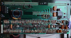
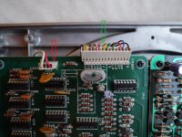
This is what the back of the logic control PCB looks like - two cut tracks and a wire bridge:

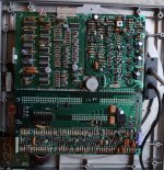
The upper side of the PCB also reveals that R221 and TR208 have been removed:

Do you think this is all that constitutes the "Start/Stop mod" and if I would just replace what's missing, bridge the tracks back and remove the wire bridge, would the original start/stop functionality be restored?
An observation that might be of interest;
SP10 service manual spec for the TR201-212 and TR218-222 is 2SC1328.
However, the PCB contains 2SC828 in all these positions and I have found references on the Net that seem to indicate that C828 is indeed the right transistor (?).
Since the 2SC828 is not available in .ZA, would it be safe to use the BC547 or BC548?
By the way, both SP10s are now perfectly well behaved after I recapped the PSUs. No more noises or vibrations. So, Start/Stop is the last remaining issue.
This is what the back of the logic control PCB looks like - two cut tracks and a wire bridge:
The upper side of the PCB also reveals that R221 and TR208 have been removed:
Do you think this is all that constitutes the "Start/Stop mod" and if I would just replace what's missing, bridge the tracks back and remove the wire bridge, would the original start/stop functionality be restored?
An observation that might be of interest;
SP10 service manual spec for the TR201-212 and TR218-222 is 2SC1328.
However, the PCB contains 2SC828 in all these positions and I have found references on the Net that seem to indicate that C828 is indeed the right transistor (?).
Since the 2SC828 is not available in .ZA, would it be safe to use the BC547 or BC548?
By the way, both SP10s are now perfectly well behaved after I recapped the PSUs. No more noises or vibrations. So, Start/Stop is the last remaining issue.
Well done on the PSU's !
Virtually any transistor is OK in those positions.
I would rebuild and check stage by stage with a scope the start/stop.
Dave
Virtually any transistor is OK in those positions.
I would rebuild and check stage by stage with a scope the start/stop.
Dave
Dave! Thanks for the encouragement - I have great success to report! Start/Stop works like a charm. No double triggering, one click start, one click stop.
R221 = 4.7k
TR208 = BC546 with "legs crossed"
Tracks bridged,
wire bridge removed.
Now I need to build the LED strobe for that one, neon gave up the ghost completely.
When you said:
or adding a little PCB with a transistor Base biased by square strobe signal, as in:
Restauration Technics SP-10 MKII • LS3/5a le forum
?
Apologies for the stupid question but I am an electronics dilettante...
R221 = 4.7k
TR208 = BC546 with "legs crossed"
Tracks bridged,
wire bridge removed.
Now I need to build the LED strobe for that one, neon gave up the ghost completely.
When you said:
were you referring to re-purposing an existing transistor in the neon circuit (which one?),Forget the strobe, and return one of the transistors via a big LED to 5v
or adding a little PCB with a transistor Base biased by square strobe signal, as in:
Restauration Technics SP-10 MKII • LS3/5a le forum
?
Apologies for the stupid question but I am an electronics dilettante...
Hi Jim
... The last one I did was to dead bug a flip-flop onto the fixed connector board and use an R-C for a debounce, three components in all, but I have the test gear to work with.
Dave
Hi!
Could you please explain this a little further. I am still working to understand the difference between the SP-10mk2 and the P-model. Is this what is needed (See picture) ?
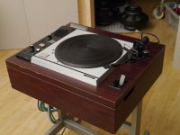
I just recently acquired two complete SL-1000mk2P. What a superb machine for fast, easy and fun vinyl playback. As the units are so easy to disassemble I will explore the potential benefits of a more substantial plinth and store the big cabinet, RIAA and the other bits in a safe place.
But then I need the start/stop to function. My SP-10mk2P looks a bit different from what I have seen of the two different BBC models.
Attachments
Well, my question turned out a bit incoherent. One more try:
Please help me restore functionality of the onboard Start/Stop switch on my SL-1000mk2P.
I uploaded some pictures of the circuitboads on my SP-10mk2P. The logic board differs a bit from the BBC models. Any help looking at them?
Thanks in advance.
Please help me restore functionality of the onboard Start/Stop switch on my SL-1000mk2P.
I uploaded some pictures of the circuitboads on my SP-10mk2P. The logic board differs a bit from the BBC models. Any help looking at them?
Thanks in advance.
Trying to understand this, as IC-17 is working as a "flip flop" and is included on this logic board, should it not be sufficient to attach a switch to in turn connect "start" and "stop" to ground? Like the red and blue wire on the connector marked with a green arrow on picture no.5 i my first post.
I am referring to page 9 in the service manual for SP-10mk2 p/l found on VE.
This is fun!
I am referring to page 9 in the service manual for SP-10mk2 p/l found on VE.
This is fun!
Last edited:
Hi all,Here is page 9 in the servicemanual
I am a proud Sp10Mk2-P/L (BBC) owner for several years now but and never had the time to restore it for home use...unitil now. The logic board contains the IC17 but I do not have the SH-10C control box. Can someone please explain the simplest way to get the local start/stop button working again ? Your help will be most appreciated.
- Status
- Not open for further replies.
- Home
- Source & Line
- Analogue Source
- Technics sp10p/l computer cable removal