Hi All,
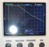
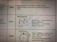
I’m adjusting per service manual after replacing caps (some were out of spec) and some diodes ( might as well while I’m in there) and I’m trying to adjust VR101 for T0 between 8 and 8.5msec. The horizontal line is roughly 1 msec on my oscilloscope, and the service manual points to somewhere in the middle of the horizontal portion of the waveform. If you look closely there’s a small bump there, which I don’t see on my oscilloscope. Do I estimate the middle of the horizontal line as the To endpoint? Any help is appreciated.
I’m adjusting per service manual after replacing caps (some were out of spec) and some diodes ( might as well while I’m in there) and I’m trying to adjust VR101 for T0 between 8 and 8.5msec. The horizontal line is roughly 1 msec on my oscilloscope, and the service manual points to somewhere in the middle of the horizontal portion of the waveform. If you look closely there’s a small bump there, which I don’t see on my oscilloscope. Do I estimate the middle of the horizontal line as the To endpoint? Any help is appreciated.
Attachments
Last edited:
Yes, the sketch is idealized, to be more clear. Looks like it is ok as-is.
Ok thanks for the response. That helps. When I switch to 45 rpm it’s at upper limit of 6.4 msec. I don’t know how precise this setting should be.