Hi,
I am desperately looking for technical information related to the wired Remote Control RC-57.
This wired remote was proposed by DENON as an option with the Denon DRM-44HX cassette deck for example.
I need to know the signals sent to the DIN connector for each button (pin, voltage, duration, etc...) and the wiring of the DIN connector.
Of course, it is an "antique" , but I cannot fnd any technical description ...
Thank you very much
...(pin, voltage, duration, etc...)...
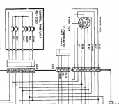
As Jon says-- it's not that complicated. The remote buttons wire just the same as the panel buttons. Straight parallel. STOP goes to a hard ground; all else goes through a switch transistor to ground (probably to disable them when invalid).
Denon DR-M44HX - Manual - Stereo Cassette Tape Deck - HiFi Engine
page 30:
Attachments

Thanks a lot : I have the SM but missed the page !...
2 additional questions to be sure that I understand how it works:
a-/.When a button is pressed, say "REW" for example, the pin 8 of the DIN connector is temporarily connected to the "Switched Ground", which is the Pin 2 of the DIN connector: this means that when "REW" is pressed, Pin 2 and Pin 8 are temporarily connected. Am I correct ?
b-/.Is such an 8 pins DIN connector still available for sale ?? it seems difficult to find ...
Thanks !
Last edited:
Thanks PRR: I had found these connectors, but I couldn't edit my previous message...
I have also studied the wiring diagram, and it seems very simple : no codes like today, only wiring...
I just believe that I will be obliged to use a set of relays, because it seems that the "switched ground" at the connector level is not the same than the "chassis ground" ??
If this is true, connecting a pin (that will be a digital output of the Arduino) to the ground will not be good: I will have to connect the pin to another "common pin" which is this "switching ground"... and therefore relays are needed ...
I already have a card to do that, but it would be simpler if a pin could simply be linked to the ground to simulate a pressed button....
The Arduino pin will be 5v or 0v whereas you require open circuit & closed circuit.
Relays have their place but for this I would try a transistor first to pull the Denon pin to ground.
Easy enough to breadboard first. Why have an Arduino drive a transistor to drive a relay if you can eliminate the relay?
Optionally, the Arduino pin could also drive an LED to indicate which pin was operational.
I assume you are using the Arduino to decode an IR remote?
- Status
- Not open for further replies.
- Home
- Design & Build
- Parts
- Techncial info on a WIRED remote control...