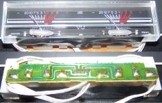
The PCB says, Meter PCB-101, TCI-ALS 94V-0, 9155010800
There is a 3wire and a 2 wire hookup, I assume the 3 wire is for L-G-R and the 2 wire is to light the lamps.
There is a 3wire and a 2 wire hookup, I assume the 3 wire is for L-G-R and the 2 wire is to light the lamps.
You will need a suitable drive circuit for the meters. Passive ones (diode/resistors/caps) suffer from lack of sensitivity. Look at manuals of old amps etc that use meters (or cassette decks) and lift the circuit from those. Often a simple one transistor stage is used.
I assume these would be classified under what people would call an "analog" VU meter correct?
I know they are not SS so they must be analog but my concern is in the type of drive circuit I should be in search of.
I know they are not SS so they must be analog but my concern is in the type of drive circuit I should be in search of.
Just rig up a variable DC PSU (battery and pot) and a series resistor. Keep your DVM across the resistor (because its internal resistance will affect the reading slightly) and adjust the pot for F.S.D. of the meter. Then just work out the current using ohms law from your DVM reading and the known series resistor.
Any meter drive circuit should work OK and will have more than enough output to drive the meters. Calibration is achieved by adjusting the input to the meter drive circuit.
Edit... or if your DVM is sensitive enough then just place it in series with the meter and resistor and read the current directly on the DVM
- Status
- Not open for further replies.
