Hi!
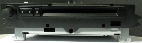
Original BMW E60 2004 head unit Harman Becker BMW E60-M-ASK on the bench.
Came in with "no audio output" according to customer.
This unit has a 4 x 35W output IC (TDA7454).
Test revealed 10VDC output on all channels but rear right.
The latter produced 100% OK audio output.
Audio at the three others too, but speakers also fed with 10VDC (don't like!).
In addition, the unit draw excessive current and output IC got very hot fast (especially when speaker load (6 Ohms) were attached!)
Unit has a fan. One defect transistor found and replaced. Fan now OK.
Thinking the lack of fan functionality caused TDA7454 to overheat and fail, I'd replace the output IC.
Power up and test: now all 4 outputs has 10VDC and unit draws the same amount of excessive current!
Thinking I might did something wrong during IC replacement, I'd replace the TDA7454 once more - this time checking thoroughly that all solderings and pcb traces were perfect.
New test: same thing. output IC overheats and 10VDC on all output channels..
Did check all pins TDA7454. Nothing "funny" except perhaps all input lines (pins 11, 12, 14 and 15) raises to 4.8VDC upon power on - which I believe is normal due to the fact that they are fed from 2pcs single ended 4558 op amps.
Lost here.
Any ideas anyone?
Attachments
Where did you buy the ICs from?
The inputs are biased to 1/2 of the supply voltage. The inputs should be capacitor isolated from the drive circuit.
The output voltage should be at 1/2 of the supply voltage, not 10v.
The inputs are biased to 1/2 of the supply voltage. The inputs should be capacitor isolated from the drive circuit.
The output voltage should be at 1/2 of the supply voltage, not 10v.
Thank you for your reply!
IC's were bought from two different locations as my local supplyer ran out (after I bough IC nr. 1 that is). Both are trusted sources and both IC's at least seems to be original manufactured by STMicroelectronics.
Both opamps (4558) seems to be OK. They are fed with 8,5VDC (pin 8) while pin 4 is connected directly to ground.
All input lines (pins 11, 12, 14 and 15) on output IC (TDA7454) idles at 4,54VDC, so I guess that's normal. Between outputs (pin 1 and 7) from both 4558's are 4 pcs ceramic capacitors (approx 920nF) in series with 2,2KOhm resistors. All those components are OK too.
Measuring directly across speaker output lines from TDA7454 (pins 7-9, 3-5, 17-19 and 21-23) I got 10,2VDC regardless whether or not speakers are connected. -Yet with speakers connected (3,5 Ohm's load), the radio draws a lot of current and output IC starts getting really hot fast! There is audio too, but very low even at max volume setting.
With all power and speakers disconnected, I measure 115 Ohms across the above mentioned speaker output lines. Lifting those pins from the board doesn't change anything (still 115 Ohms), so I guess the IC is damaged again.. :-(
Could of course try to replace it once more, but then it will probably just fail over again.
Need to be certain that everything is 100% OK, but where to look?
ps: You say the output voltage should be 1/2 of the supply voltage? I believe you where talking bout the 4558's, not the TDA7454 right?
12v ICs that operate off of a single-ended supply (12v to ground, not +12v to -12v) that are rated for 20w/ch (RMS) have to operate in bridged mode and must be biased to 1/2 of the supply voltage to produce rated power. A typical car audio head unit has ~6.5v DC on every speaker output wire. The diagram below is from a pioneer head unit and shows typical voltages.
Attachments
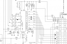
Thanks! The diagram however shows 7V on all output lines (both + and -) with respect to chassis ground. That will make 0V between the pairs - which of course leaves no DC output directly to the speakers.
In my case though, I got 10,2VDC on all +sides from the output IC and 0V on all -sides.
Measuring between the minus sides and chassis ground during power on, I actually read only 30 Ohms! Powering off the unit makes Ohm go infinite then drops to approx 8kOhm.
Seems the output IC almost "grounds" its speakers minus side outputs during power on.
Strange.. :-(
I see that pin 16 on my TDA7454 is used for selecting operation mode. This pin is permanently grounded (and have always been), so I guess that operation mode is OK too.
Will try to check some capacitors next.
Thanks again!
Did some "testing"..
Tied down all 4 input lines (TDA7454-side) to ground level. Now the output IC doesn't draw excessive current anymore and no DC to speakers (no sound either for that matter 🙂 )
All 8 speaker output legs now measures approx 3,6VDC and no overheating.
Could it be that this chip actually need some sort of "pull-down-resistors" at the inputs to prevent them from running wild and that all brand new chips will act this way even when only VCC, stand-by and GND are connected? Sounds strange to me too though..
Yet, when I lift all 4 input legs from the board, the chip goes crazy again. Seems the input DC-level must raise to above 3,9VDC before the excessive current draw begins.
Further experimenting also reveals that any combination of only 3 input legs grounded also will do the "trick". Once one of them is no longer grounded, excessive current draw starts.
Beginning to wonder if the TDA7454 really is bad..
ps: Do you also have a diagram showing the opamp that feeds the PAL007A you enclosed? Was wondering what voltages revolved that one too.
I would suspect that the IC is DC coupled throughout and any drive that pulls the input from it's biased voltage (1/2 supply) should drive the output as well.
It's driven by an electronic volume control IC. The output is 4v. The input caps isolate the 4v drive from the 7v input. It's split between page 20 and 21.
http://www.bcae1.com/temp/pioneer - DEH-P550_DEH-5500_DEH-5550MP.pdf
It's driven by an electronic volume control IC. The output is 4v. The input caps isolate the 4v drive from the 7v input. It's split between page 20 and 21.
http://www.bcae1.com/temp/pioneer - DEH-P550_DEH-5500_DEH-5550MP.pdf
They have 3 output states with a control mechanism. Single-ended, high efficiency btl, and full btl. The datasheet shows the mechanism involves switching of negative speaker lines to achieve these states, which the OP has reported something strange with these lines. As he said pin 16, however the chip will switch states based on temperature regardless of pin 16 state as well.
Last edited:
As far as I can see, with no input, the input and output should be at 1/2 of the supply voltage. The various states all operate at 1/2v, unless I'm missing something.
Neither should non of those operational states make the speaker negative output lines go grounded..
Agree on the 1/2Vcc on both input and output side with no in- or output connected. The chip in use here simply cannot be healthy.
I'll order 2 more from a third source and do a throughout test (off board) before installing them.
Thanks to you both so far!
Agree on the 1/2Vcc on both input and output side with no in- or output connected. The chip in use here simply cannot be healthy.
I'll order 2 more from a third source and do a throughout test (off board) before installing them.
Thanks to you both so far!
Bear in mind that the output will only be 1/2v if there is nothing affecting the voltage on the input. The IC has 26dB of gain. That means that only 0.3v above or below the input bias voltage to cause the output to swing full positive and negative.
If the output positive and negative aren't precisely the same magnitude above and below the bias voltage when the input is driven from the bias voltage, that would tend to indicate that the ICs are defective.
If the output positive and negative aren't precisely the same magnitude above and below the bias voltage when the input is driven from the bias voltage, that would tend to indicate that the ICs are defective.
Okey..
Just removed the IC and cleaned the PCB 200%
Did some measurements after powering on the unit.
These are my readings:
Pin 4 (st-by): 4.85V
Pin 6 and 20: (Vcc1 and Vcc2): 13.48V (clean DC)
Pin 10 (SVR): 330mV
Pin 22 (mute): 4.85V
Pin 25 (cd): 4.93V
Pins 1, 2, 8, 13, 16, 18 and 24 are all grounded.
All input pins (11, 12, 14 and 15) read approx +4V at the touch of probe, then dropped to below 1V. When unit was turned off, the meter read -4V raising to 0V after a while.
I also did connect all of these 4 inputs (one by one) to my external amplifier: 100% great sound on radio and CD and volume control functioned perfectly!
Then; what could possibly go wrong here when I attach the new IC?
There IS a loud pop in speakers though when I power on the unit. Could it be that the opamps feed some sort of "power-spike" to the inputs and damage them? 😕
Anyway; 115Ohms between all 4 output pairs (disconnected) is not right.
I'll get back with the results here when new IC's has arrived..
Regards (from sceptical 😱)
OK. Just got the new IC's (TDA7454).
Seems those 115 Ohms between all 4 output pairs are correct (tested off the board upon arrival).
Mounted and new test: exactly the same result! :-(
Got the unit now hooked up with 4 pcs. identical speakers 4 Ohms.
Playing a CD and the unit does produce sound, but even at max volume, my iPod is louder (from its headphone output)..
The unit draws 5.2 Amps while playing (from car battery 13.7VDC) and all 4 speaker pairs measure 8.9VDC (between + and -).
Temperature measured with IR-thermometer reveals approx. 60 deg. Celcius at heat sink (too hot to touch!).
Unit is fully assembled. Fan does kick in from time to time.
May have altered the topic here, because the IC's actually doesn't keep blowing.
But those 9VDC at the outputs still puzzles me.
All readings seems correct - yet the chip keeps pumping DC to its speakers and low volume output..
I'm now convinced though that these TDA7454's have been OK all the time (except for the first one I did replace).
I've tried running 2 speakers connected to only the + output lines. Got stereo and sound (unit now draws 1.2 Amps and no DC on speakers), but still too low output (and only 2 channels)..
Didn't want to toss this unit. A "new" one costs around $740.
What the heck is the matter with this thing?!!
Any more suggestions anyone?
Anyone know a similar car radio that used this audio output IC and may have a schematic? (yes I've searched the net..)
:frustrated:
Are you sure that something isn't pulling the input from its bias point (that would cause DC offset)?
Have you tried completely disconnecting the input pin of the IC for one channel to see if the offset on that channel would go to 0v?
Have you tried completely disconnecting the input pin of the IC for one channel to see if the offset on that channel would go to 0v?
hmm.. believe I did so in posting #6
Would you like me to try that once more? With only one input pin fully disconnected?
Would you like me to try that once more? With only one input pin fully disconnected?
Just lifted pin 1 from one of the two 4558's (confirmed lifted as DC on that pin now raised to just below Vcc level on pin 8). This pin goes directly to a ceramic smd-capacitor then via a 2K2 Ohm smd-resistor and then directly to pin 12 on the output IC (rear right channel input).
Testing: absolute NO changes in anything! Same DC offset on all speaker outputs and even sound at the rear right output!!
This is getting stranger each second..
Testing: absolute NO changes in anything! Same DC offset on all speaker outputs and even sound at the rear right output!!
This is getting stranger each second..
I ordered one of these to see if I could duplicate what you're seeing. I should get it in a few days.
Many thanks, Perry!
I've reconnected all the pins now and done some more "research" though.
It seems jerluwoo may have a point regarding pin 16 on this chip!
I just lifted it from the board and now the radio works 100% as it should!
Tracing its path (by visual only) it seems that it ends up in a safety smd-resistor (0Ohm) which is grounded.
If this is the case - the original TDA7454 must actually differ in behavior from those I newly bought!
All measurements now read in accordance to your theorys about half Vcc and so on.
6.8VDC on both + and - output pins on all 4 channels (hence no DC).
I'm gonna fully assemble the unit now and do a throughout test!
- Status
- Not open for further replies.
- Home
- General Interest
- Car Audio
- TDA7454 keep blowing