Hi all,
I've been working on a parallel 'deluxe' board from China but unfortunately no schematic. I don't understand the reasoning for the RC circuit they added across the feedback resistor as well as how they calculated the component values. I don't think it's an RC oscillator cicuit, but could be wrong. The cap in circuit is actually 47 pF multi layer ceramic. Anyone any ideas?
Thanks
Attachments
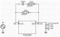
I don't understand the reasoning for the RC circuit they added across the
feedback resistor as well as how they calculated the component values.
See the discussion here for similar considerations with the LM3886.
LM3886 Chip Amp Stability Analysis
I suspect they have had stability problems.
The feedback resistor path on a chip amp should be as short as possible.
1mm = 1nH of inductance which causes phase shift.
The 7293 and 7294 also have a min gain to keep stability.
The feedback resistor path on a chip amp should be as short as possible.
1mm = 1nH of inductance which causes phase shift.
The 7293 and 7294 also have a min gain to keep stability.
- Status
- Not open for further replies.